1. Introduction
| A | B | C |
|---|---|---|
| 0 | 0 | 0 |
| 0 | 1 | 0 |
| 1 | 0 | 0 |
| 1 | 1 | 1 |
In contrast, OR logic results to a high value (1) when either of the input becomes a high value (1). In pneumatic, the shuttle valve performs the OR logic operation. The truth table indicate the response of the OR logic corresponding to a pair of input.
| A | B | C |
|---|---|---|
| 0 | 0 | 0 |
| 0 | 1 | 1 |
| 1 | 0 | 1 |
| 1 | 1 | 1 |
In the next section, the AND and OR logic is implemented in reference to the set of problem or scenario. Shuttle valve is also known as double control valve or double check valve. A shuttle valve has two inlets and one outlet. At any one time, flow is shut off in the direction of whichever inlet is unloaded and is open from the loaded inlet to the outlet. This valve is also called an OR valve. A shuttle valve may be installed for example, when the cylinder or valve is to be actuated from two points, which may be remote from one another. The problem are:
(AND Logic). The piston rod of a double acting cylinder is to advance only if a work piece is inserted in the retainer, a guard has been lowered and the operator presses the push button valve. Upon release of the push button or if the guard is no longer in its lower position, the cylinder is to retract to initial position.
(OR Logic). A double-acting cylinder is used to transfer parts from one point A to point B. If either a push button or a foot pedal is operated, the cylinder is extended. A 3/2 way roller lever valve is to be used to detect the full extension of the cylinder.
2. Method and Simulations
2.1 AND Logic
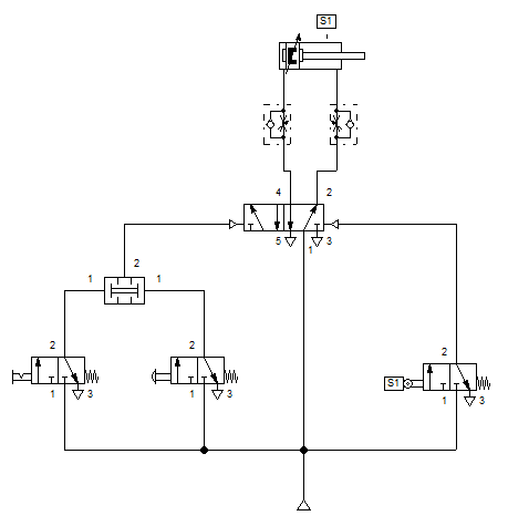
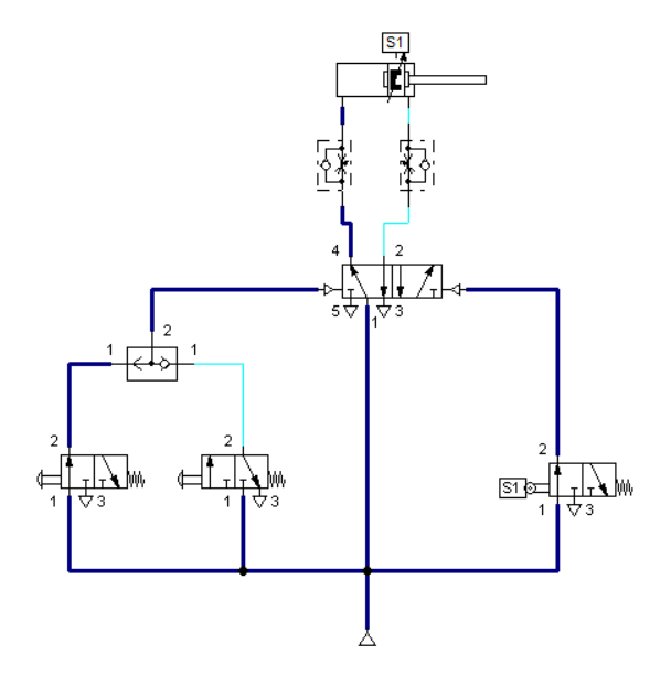
A pair of 3/2 way directional valve with push button serve as the input for the dual pressure valve in Figure 1. The circuit is built from the indirect control by which the intermediate valve have both pneumatic actuation ports. The port 15, at which the 3/2 way directional valve with limit switch (sensor S1) is placed, retracts the cylinder when it reaches the full extension. On the other side, port 14 controls the extension of the double-acting cylinder. As stated in the scenario, two push button are needed to actuate the cylinder and it must be simultaneously pressed. We interpret it as an AND logic function. We used a dual pressure valve to perform the function in a pneumatic system.
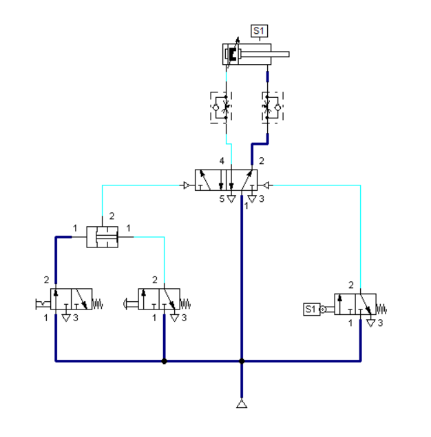
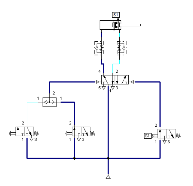
When a single push button is pressed in Figure1, the dual pressure valve remains closed hence the other port do not have an air intake to it, as shown in Figure 2. In similar way, when the other push button is pressed, the same result happen unless both push buttons are pressed simultaneously.
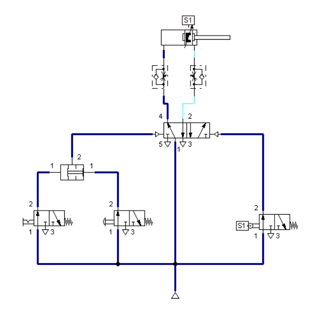
In Figure 3, the double-acting cylinder extends because both push button are pressed. Dual pressure valves switches from close to open state when both of its input port experiences build up of air pressure.
2.2 OR Logic
For the OR logic, we used a shuttle valve to translate the logical OR function into pneumatic. All the valves is connected to 3/2 way valve with push button in left and right actuation. The inputs of the shuttle valve are connected to the working connections of the valves which is both 3/2 way valve manually operated . The circuit is shown in Figure 4.
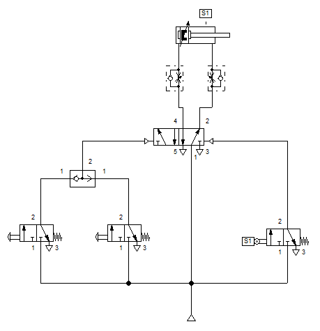
Once a push button is pressed, the corresponding 3/2 way directional control valve is actuated and a signal is transmitted to the input port of the shuttle valve. The OR condition is fulfilled and the signal passes through the shuttle valve and is emitted at port 2. The signal pressure is prevented from escaping via the exhaust of the unactuated valve by closing the line in the shuttle valve. The signal effects the switching of the control element 5/2 way valve pneumatically operated. The piston side of the cylinder is pressurized and the piston rod advances. The 3/2 way roller lever valve is used to retract the cylinder back to its original position. This is visually shown in Figure 5.
3. Conclusion
In an AND logic in pneumatic, a dual pressure valve requires two pressurized inputs to allow an output from itself. It is an interlock control that means it is only possible to operate when a pair of condition is achieved. A classic example is a pneumatic system that works only when its safety door is closed and its manual control valve is operated. The flow passage will open only when both control valves are operated. In contrast, OR logic allows one activating condition to operate. When either actuation mechanism is connected to shuttle valve, the cylinder extends once one of the actuation is triggered. OR logic is an example of remote control of a pneumatic circuit wherein a push button can either be local to the system or remote in the control room.
4. Reference
[1] Pneumatic Basic Level. online access
[2] Pneumatic Advanced Level. online access
(Note: All images and diagram in the text are drawn by the author (@juecoree) except those with separate citation.)
If your are Interested in Pneumatic Basics, you can read the other posting:
1. Pneumatic Basics: Direct Control
2. Pneumatic Basics: Indirect Control
Posted with STEMGeeks