Our best friend in the PIC
Shoutout to PIC Microcontroller Projects

In this article you'll find:
- Introduction
- ADC conversion in a PIC
- Instructions for the ADC
- PIC Connections
- Setting the code
Greetings to all!
In the previous edition, we took a look at the ADC process, where we converted an analog signal (which has a value that changes continuously), into a discrete signal (signal with two states: High and Low) that digital devices can interpret.
Once we know this, we can move on to applying the concept of Analog to Digital conversion in practice.
In this case, we will see how we can take the analog information from any sensor or change in resistance, impedance or capacitance, to be able to observe it digitally at the output.
If you want to know how to do this, just keep reading.
ADC conversion in a PIC
Shoutout to Analog Devices Wiki
I won't go into this section too much. If you want to know how an ADC works, you just have to read the previous article in this series, which explains it in detail.
If you want a short description of the ADC process, it refers to the conversion of a signal that changes continuously over time, which can be electrical, audio or other quantities, and converts it into sequences of 1s and 0s that it can understand. the microcontroller.
Although we have individual ADC converters in the form of integrated ones, with PIC microcontrollers it is not necessary to buy other ADCs, since these usually come with ADCs included, giving us the option of using one of their ports as an ADC channel.
For example, for the PIC16f877a, it has 8 ADC channels, which are located on the input/output pins of port A.
These ADC ports can be configured according to what the user wants, accessing registers such as ADCCON in the PIC and changing the state of some of its bits.
However, since we will be using a high-level language like C, we will only have to pay attention to a few instructions. These are:
Instructions for the ADC
Shoutout to Joseph Burgess in SlidePlayer
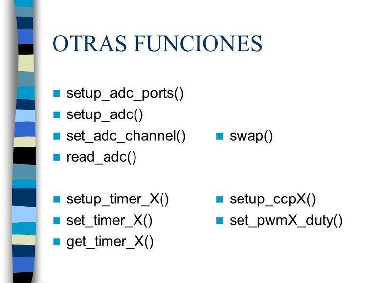
Managing the ADC through the C language is really simple, we just have to pay attention to the following instructions:
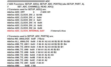
- setup_adc_ports() ; With this, we select which of the PIC pins or ports we will use as analog input. For this, we can use the following as parameters:
Shoutout to hernando gomez palencia in issuu
Where the explanation is simple. If we want to use only one of the pins, we would use AN0, AN1, AN2... as a parameter.
If we want to use more than 1, we use AN0_AN1_AN2 and as many ports as we want.
If we are going to use all the pins of port A, we simply set ALL_ANALOG
When we want to use pins RA2 and RA3 as the Reference Voltage pins, which allow us to change the full scale or maximum voltage of the ADC, we add VREF_VREF as parameters, which will add pin 2 of port A as the Vref- and pin 2 as Vref+
In this case, we will use AN0, since we want to use pin 0 of port A as a channel for the ADC.
- setup_adc(); This is used to configure the ADC conversion mode. Generally, the internal clock of the ADC is used, although frequency dividers can also be used for some operations (See the image above).
For the purposes of the tutorial, the internal one will be used, which will be adc_clock_internal.
setup_vref() ; With this we activate the use of pins RA2 and RA3 as Vref+ and Vref-, which will help us determine the maximum voltage reached by the highest value of the ADC. For example, if we used a voltage of 3.3V in the Vref+, now 1023 of the 10-bit ADC would represent 3.3V.
set_adc_channel(); This instruction allows us to select the ADC channel from which we are going to read. For example, if with setup_adc_ports(), we select RA0 as the channel for the ADC, then we must set set_adc_channel(0), to read this channel.
read_adc(); It is with this that the channel that we previously indicated to the ADC with set_adc_channel() is read.
Now that we know how each instruction works, it is time to create a program that allows us to read the value of a potentiometer on pin 0 as a digital value. Let's see how the connections are made.
PIC Connections
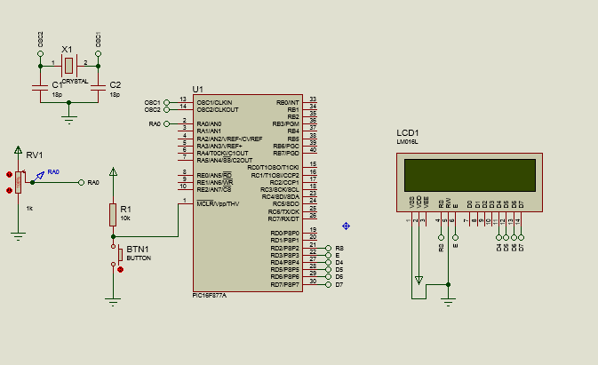
Regarding the way in which we must make the connections between the PIC and the peripherals, according to the image, we can see that the PIC is connected in the same way as in previous editions to a 20MHz oscillator crystal in conjunction with two 18pF ceramic capacitors.
Likewise, we also have our button between ground and a pullup resistor to ensure that the PIC is reset when pressed.
Regarding the way we interlock the 16x2 LCD with the PIC, we use the same configuration, connecting data pins D4, D5, D6 and D7 to pins RD4, RD5, RD6 and RD7 of port D, while the Register Select pin connects to RD2 and the Enable pin connects to RD3. If you want to know about the details behind this connection, read the following article
And finally, the only different element will be a potentiometer connected between its two input ends to ground and to the power supply, while the output will go to the RA0 pin, where our ADC channel will be.
Once the Hardware is configured, we only have to start with the code.
Setting the code
We start with the configuration of our program, which will be almost identical to that used in previous editions.
#include <16f877a.h>
#fuses HS, NOWDT, NOPROTECT, NOPUT, NOLVP, BROWNOUT
#deviceADC = 10
#use delay(clock=20M)
#use standard_io(D)
Here, the only change we can notice is the use of the #device ADC = 10 directive, with which we determine the number of bits that the ADC will have to use, this is because the internal ADCs of the PIC can also be reduced to 8 bits .
Subsequently, we proceed to define the pins dedicated to the LCD and include its library.
#define LCD_DB4 PIN_D4
#define LCD_DB5 PIN_D5
#define LCD_DB6 PIN_D6
#define LCD_DB7 PIN_D7
#define LCD_RS PIN_D2
#define LCD_E PIN_D3
#include <LCD_16X2.c>
Then, before moving to the main function main and the while loop, we must define the variable that we will use to store the data that we read from the ADC. This will be a variable of type long or int16, since the possible values will be greater than the 255 (11111111) that the int supports.
long adc_value
And if we analyze what happens inside the void main() and the while loop:
void main()
{
    setup_adc_ports(AN0);
    lcd_init();
    setup_adc(adc_clock_internal);

    while(TRUE)
    {
       set_adc_channel(0);
       delay_us(2);
       adc_value = read_adc();

       lcd_gotoxy(1,1);
       printf(lcd_putc, "ADC: %Lu", adc_value);
    }
}
We can notice that the first thing to do before the while(TRUE) loop is executed infinitely, will be to use setup_adc_ports(AN0), to choose pin 0 of port A as the ADC channel.
Next, we start the lcd with lcd_init() and proceed to select the conversion mode with setup_adc(), where we choose adc_clock_internal to use the internal clock of the ADC.
Once we are in the cycle, we access channel 0 (AN0 pin) of the adc with set_adc_channel and wait for the conversion to finish with a small delay of 2 microseconds (delay_us), and then enter the value that we created in the variable that we created. we read from pin AN0 with read_adc()
Once we do this, we only have to access the first row and column of the LCD screen and with printf (A format string), use the lcd_putc() command of the lcd, to write a long unsigned integer (This is why the %Lu), which will be the variable for the ADC value.
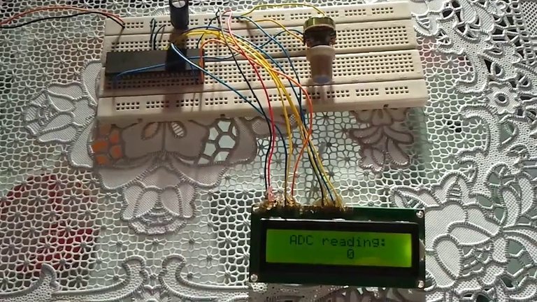
In this way, we compile this program and run it in Proteus or send it to our PIC with PICKit:
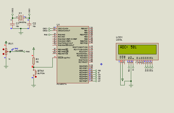
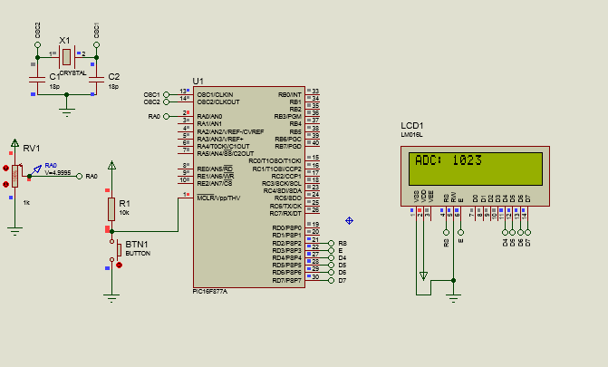
We can notice that as indicated by the voltage meter and the LCD screen, when we vary the resistance of the potentiometer, so will the voltage, and therefore, when converted to ADC values, so will the digital value shown on the screen. screen. For example, if we take the value of 2.4499V, we know that we will have the value of 501 in the ADC, which complies with the formula to calculate the value of the ADC with 5V as full scale:
adc value (10 bits)= Vi * 1023 = 2.4499V * 1023 = 501
                     ---------   --------------
                Vref           5V
In this way, the complete code would look like this:
#include <16f877a.h>
#fuses HS, NOWDT, NOPROTECT, NOPUT, NOLVP, BROWNOUT
#deviceADC = 10
#use delay(clock=20M)
#use standard_io(D)

#define LCD_DB4 PIN_D4
#define LCD_DB5 PIN_D5
#define LCD_DB6 PIN_D6
#define LCD_DB7 PIN_D7
#define LCD_RS PIN_D2
#define LCD_E PIN_D3
#include <LCD_16X2.c>

long adc_value;

void main()
{
    setup_adc_ports(AN0);
    lcd_init();
    setup_adc(adc_clock_internal);

    while(TRUE)
    {
       set_adc_channel(0);
       delay_us(2);
       adc_value = read_adc();

       lcd_gotoxy(1,1);
       printf(lcd_putc, "ADC: %Lu", adc_value);

    }
}
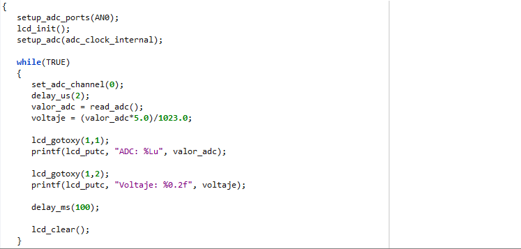
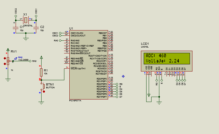
And if we wanted to add the value in volts on the LCD screen at the same time, we would only have to create another variable, now of type float (Since we will work with decimal values of volts), where once the adc reading is done and the save in adc_value, we just have to clear the formula for the ADC value and get the volts:
Vi =    ADC value * Vref
      ------------------------
        1023
Which translates into the following code:
long adc_value;
float voltage;

void main()
{
    setup_adc_ports(AN0);
    lcd_init();
    setup_adc(adc_clock_internal);

    while(TRUE)
    {
       set_adc_channel(0);
       delay_us(2);
       adc_value = read_adc();
       voltage = (adc_value*5.0)/1023.0;

       lcd_gotoxy(1,1);
       printf(lcd_putc, "ADC: %Lu", adc_value);

       lcd_gotoxy(1,2);
       printf(lcd_putc, "Voltage: %0.2f", voltage);

       delay_ms(100);

       lcd_clear();
    }
}
Where in addition to adding the new variable, we assign the value of the formula after reading the adc.
Then, we go to row 2 in position 1 to add as a format string the voltage value with a float with 2 decimal places (f for the float, and 0.2 for the number of decimal places).
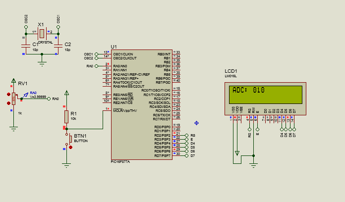
Finally, we place a small delay before cleaning the LCD. This is to avoid the flickering effect that can prevent us from seeing the values in the ADC properly. This would look like this when running the program on the PIC:
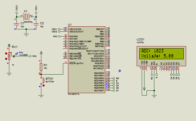
And in this way we will have our program for ADC conversion.
I hope that this article, linked to its predecessor, can show the importance of ADC and its usefulness when working with PICs.
Whether for the use of sensors or communication protocols, this will be of vital importance for future projects with our microcontrollers.
In the next edition, we will see how we can use multiple ADC channels to our advantage and what we can apply them to. Without more to say:

Nuestro mejor amigo en los PIC
Shoutout to PIC Microcontroller Projects
In this article you'll find:
- Introducción
- Conversión ADC en un PIC
- Instrucciones para el ADC
- Conexiones del PIC
- Estableciendo el código
¡Un saludo a todos!
En la edición previa, dimos un vistazo al proceso de ADC, donde convertíamos una señal analógica (Que tiene un valor que cambia continuamente), en una señal discreta (señal con dos estado: Alto y Bajo) que los dispositivos digitales pueden interpretar.
Una vez que sabemos esto, ya podemos pasar a aplicar el concepto de la conversión Analógica a Digital en la práctica.
En este caso, veremos como podemos tomar la información analógica de cualquier sensor o cambio en resistencia, impedancia o capacitancia, para poder observarla de manera digital a la salida.
Si quieres saber como hacer esto, solo tienes que seguir leyendo.
Conversión ADC en un PIC
Shoutout to Analog Devices Wiki
No me extenderé mucho en esta sección. Si quieres saber como funciona un ADC, solo tienes que leer el artículo previo de esta serie, que lo explica en detalle.
Si quieres una descripción corta del proceso de ADC, este se refiere a la conversión de una señal que cambia continuamente con el tiempo, la cual puede ser eléctrica, de audio u otras magnitudes, y la convierte en secuencias de 1 y 0 que puede entender el microcontrolador.
Si bien, tenemos convertidores ADC individuales en forma de integrados, con los microcontroladores PIC no hace falta comprar otros ADC, puesto que estos suelen venir con ADCs incluidos, dándonos la opción de utilizar alguno de sus puertos como canal ADC.
Por ejemplo, para el PIC16f877a, este tiene 8 canales ADC, que se encuentran en los pines de entrada/salida del puerto A.
Estos puertos ADC pueden ser configurados de acuerdo a lo que el usuario desee, accediendo a registros como ADCCON en el PIC y cambiando el estado de algunos de sus bits.
Sin embargo, ya que usaremos un lenguaje de alto nivel como el C, solo tendremos que prestar atención a algunas instrucciones. Estas son:
Instrucciones para el ADC
Shoutout to Joseph Burgess in SlidePlayer
El manejo del ADC por medio del lenguaje C es realmente sencillo, solo tenemos que prestar atención a las siguientes directas:
- setup_adc_ports() ; Con esta, seleccionamos cual de los pines o puertos del PIC usaremos como entrada analógica. Para esto, tenemos que se pueden usar como parámetros los siguientes:
Shoutout to hernando gomez palencia in issuu
Donde la explicación es simple. Si queremos usar solo uno de los pines, usaríamos como parámetro a AN0, AN1, AN2...
Si queremos usar más de 1, se usa AN0_AN1_AN2 y cuantos puertos queramos.
Si vamos a usar todos los pines del puerto A, simplemente colocamos ALL_ANALOG
Cuando queremos usar a los pines RA2 y RA3 como los de Voltaje de Referencia, que nos permiten cambiar el fondo de escala o voltaje máximo del ADC, agregamos como parámetros VREF_VREF, que añadirán al pin 2 del puerto A como el Vref- y al pin 2 como Vref+
En este caso, usaremos AN0, ya que queremos usar el pin 0 del puerto A como canal para el ADC.
- setup_adc(); Este se usa para configurar el modo de conversión del ADC. Por lo general se suele usar el reloj interno del ADC, aunque también se pueden usar divisores de frecuencias para algunas operaciones (Observar la imagen de arriba).
Para efectos del tutorial, se usará el interno, que será adc_clock_internal.
setup_vref() ; Con este activamos el uso de los pines RA2 y RA3 como Vref+ y Vref-, que nos servirán para determinar el voltaje máximo que alcanza el valor más alto del ADC. Por ejemplo, si usaramos en el Vref+ un voltaje de 3.3V, ahora 1023 del ADC de 10 bits representaría 3.3V.
set_adc_channel(); Esta instrucción nos permite seleccionar el canal del ADC del que vamos a realizar la lectura. Por ejemplo, si con setup_adc_ports(), seleccionamos a RA0 como el canal para el ADC, entonces debemos de colocar a set_adc_channel(0), para leer este canal.
read_adc(); Es con este que se realiza la lectura del canal que indicamos anteriormente al ADC con set_adc_channel().
Ahora que sabemos como funciona cada instrucción, es tiempo de crear un programa que nos permita leer el valor de un potenciómetro en el pin 0 como valor digital. Veamos como se realizan las conexiones.
Conexiones del PIC
Con respecto a la forma en la que debemos de realizar las conexiones entre el PIC y los periféricos, según la imagen, podemos observar que el PIC se encuentra conectado de igual manera que en las ediciones anteriores a un cristal oscilador de 20MHz en conjunción con dos capacitores cerámicos de 18pF.
Así mismo, también tenemos nuestro botón entre la tierra y una resistencia pullup para garantizar que se resetee el PIC cuando se presione.
Con respecto a la forma en la que entrelazamos la pantalla LCD 16x2 con el PIC, usamos la misma configuración, conectando los pines de datos D4, D5, D6 y D7 a los pines RD4, RD5, RD6 y RD7 del puerto D, mientras que el pin de Register Select se conecta al RD2 y el de Enable a RD3. Si quieres saber sobre los detalles detrás de esta conexión, lee el siguiente artículo
Y finalmente, el único elemento distinto será un potenciómetro conectado entre sus dos extremos de entrada a tierra y a la alimentación, mientras que la salida irá hacia el pin RA0, donde estará nuestro canal ADC.
Una vez que el Hardware se encuentra configurado, solo nos queda comenzar con el código.
Estableciendo el código
Comenzamos con la configuración de nuestro programa, que será casi idéntica a la utilizada en ediciones anteriores.
#include <16f877a.h>
#fuses HS, NOWDT, NOPROTECT, NOPUT, NOLVP, BROWNOUT
#device ADC = 10
#use delay(clock=20M)
#use standard_io(D)
Aquí, el único cambio que podemos notar es el uso de la directiva #device ADC = 10, con la que determinamos la cantidad de bits que tendrá el ADC a usar, esto debido a que los ADC internos del PIC también pueden reducirse a 8 bits.
Posteriormente, procedemos a definir los pines dedicados al LCD y a incluir la librería de este.
#define LCD_DB4 PIN_D4
#define LCD_DB5 PIN_D5
#define LCD_DB6 PIN_D6
#define LCD_DB7 PIN_D7
#define LCD_RS PIN_D2
#define LCD_E PIN_D3
#include <LCD_16X2.c>
Luego, antes de pasar a la función principal main y al ciclo while, debemos de definir la variable que usaremos para almacenar los datos que leamos del ADC. Esta será una variable de tipo long o int16, ya que los valores posibles llegarán a ser mayores que los 255 (11111111) que soporta el int.
long valor_adc
Y si analizamos lo que pasa dentro del void main() y el ciclo while:
void main()
{
   setup_adc_ports(AN0);
   lcd_init();
   setup_adc(adc_clock_internal);

   while(TRUE)
   {
      set_adc_channel(0);
      delay_us(2);
      valor_adc = read_adc();

      lcd_gotoxy(1,1);
      printf(lcd_putc, "ADC: %Lu", valor_adc);
   }
}
Podemos notar que lo primero a realizar antes de que se ejecute el ciclo while(TRUE) infinitamente, será usar setup_adc_ports(AN0), para escoger al pin 0 del puerto A como el canal del ADC.
Luego, iniciamos el lcd con lcd_init() y procedemos a seleccionar el modo de conversión con setup_adc(), donde escogemos el adc_clock_internal para usar el reloj interno del ADC.
Una vez que estamos en el ciclo accedemos al canal 0 (El pin AN0) del adc con set_adc_channel y esperamos a que finalice la conversión con un pequeño delay de 2 microsegundos (delay_us), para luego, introducir en la variable que creamos el valor que leímos del pin AN0 con read_adc()
Una vez realizamos esto, solo tenemos que acceder a la primera fila y columna de la pantalla LCD y con printf (Un format string), usar el comando de lcd_putc() del lcd, para escribir para escribir un entero largo sin signo (Por esto el %Lu), que será la variable para el valor del ADC.
De esta forma, compilamos este programa y lo ejecutamos en Proteus o lo envíamos a nuestro PIC con el PICKit:
Podemos notar que según nos indica el medidor de voltaje y la pantalla LCD, cuando variamos la resistencia del potenciómetro, también lo hará el voltaje, y por lo tanto, al ser convertidos a valores de ADC, también lo hará el valor digital mostrado en la pantalla. Por ejemplo, si tomamos el valor de 2.4499V, sabemos que tendremos el valor de 501 en el ADC, lo cual cumple con la fórmula para calcular el valor del ADC con 5V como fondo de escala:
valor del adc (10 bits)= Vi * 1023 = 2.4499V * 1023 = 501
                         ---------   --------------
                            Vref           5V
De esta forma, el código completo se vería de la siguiente manera:
#include <16f877a.h>
#fuses HS, NOWDT, NOPROTECT, NOPUT, NOLVP, BROWNOUT
#device ADC = 10
#use delay(clock=20M)
#use standard_io(D)

#define LCD_DB4 PIN_D4
#define LCD_DB5 PIN_D5
#define LCD_DB6 PIN_D6
#define LCD_DB7 PIN_D7
#define LCD_RS PIN_D2
#define LCD_E PIN_D3
#include <LCD_16X2.c>

long valor_adc;

void main()
{
   setup_adc_ports(AN0);
   lcd_init();
   setup_adc(adc_clock_internal);

   while(TRUE)
   {
      set_adc_channel(0);
      delay_us(2);
      valor_adc = read_adc();

      lcd_gotoxy(1,1);
      printf(lcd_putc, "ADC: %Lu", valor_adc);

   }
}
Y si quisieramos añadir al mismo tiempo el valor en voltios en la pantalla LCD, solo tendríamos que crear otra variable, ahora de tipo float (Ya que trabajaremos con valores decimales de voltios), donde una vez que se realice la lectura del adc y se guarde en valor_adc, solo tenemos que despejar la fórmula para el valor del ADC y obtener los voltios:
Vi =    Valor de ADC * Vref
     ------------------------
                1023
Lo que se traduce en el siguiente código:
long valor_adc;
float voltaje;

void main()
{
   setup_adc_ports(AN0);
   lcd_init();
   setup_adc(adc_clock_internal);

   while(TRUE)
   {
      set_adc_channel(0);
      delay_us(2);
      valor_adc = read_adc();
      voltaje = (valor_adc*5.0)/1023.0;

      lcd_gotoxy(1,1);
      printf(lcd_putc, "ADC: %Lu", valor_adc);

      lcd_gotoxy(1,2);
      printf(lcd_putc, "Voltaje: %0.2f", voltaje);

      delay_ms(100);

      lcd_clear();
   }
}
Donde además de agregar la nueva variable, asignamos el valor de la fórmula después de leer el adc.
Luego, nos dirigimos a la fila 2 en la posición 1 para añadir como foramt string el valor de voltaje con un float con 2 decimales (f para el float, y 0.2 para el número de decimales).
Finalmente, colocamos un pequeño retardo antes de limpiar el lcd. Esto para evitar el efecto de parpadeo que puede impedirnos ver bien los valores en el ADC. Esto se vería de la siguiente manera al ejecutar el programa en el PIC:
Y de esta forma tendremos nuestro programa para conversión ADC.
Espero que este artículo, ligado a su antecesor, pueda mostrar la importancia del ADC y la utilidad de este al trabajar con los PIC.
Ya sea para el uso de sensores o protocolos de comunicación, este será de vital importancia para futuros proyectos con nuestros microcontroladores.
En la siguiente edición, veremos como podemos utilizar multiples canales del ADC a nuestro favor y a que podemos aplicarlos. Sin más que decir:
Esta increíble como funciona, apenas se cosas simples de electrónica pero esto esta a un nivel superior para mi.
Saludos amigo. No te preocupes, trataré de escribir más artículos de electrónica explicando lo que haga falta para entender como usar microcontroladores.
Sigue con el excelente trabajo en los artículos de HTML y CSS. Feliz día.
Thanks for your contribution to the STEMsocial community. Feel free to join us on discord to get to know the rest of us!
Please consider delegating to the @stemsocial account (85% of the curation rewards are returned).
You may also include @stemsocial as a beneficiary of the rewards of this post to get a stronger support.