Hello. Here is my new post!
Today I wanna show you my microcontroller I have build one year ago in school.
It looks like this:
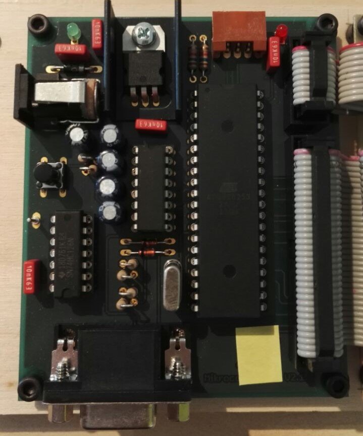
Ignore the yellow piece of paper ^-^
The PCB was made by a company and the layout was made by my teacher. The soldering was my part xD.
I know some parts are not in perfect position.
The next picture shows three areas which have different tasks
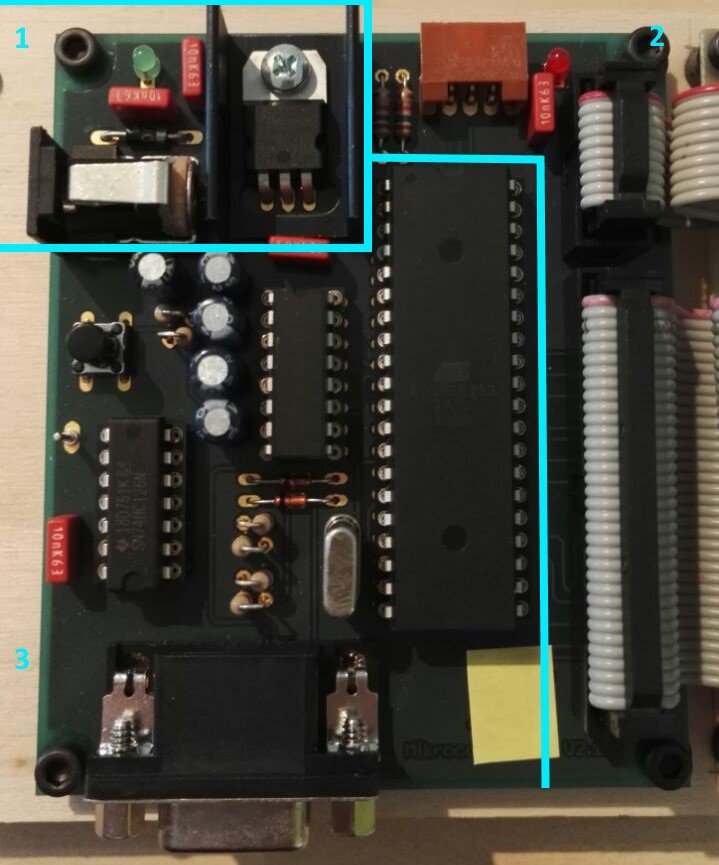
Area 1 shows the voltage regulation. It converts the input voltage to 5V
Area 2 shows the outputs. Two ribbon cables at the right and at the top there is a brown plug strip. It is used for the I2C bus-system.
Area 3 shows the processor itself and all necessary components to make it work. There is also a D-Sub plug to programm the processor.
The ribbon cables are connected to this IO-card
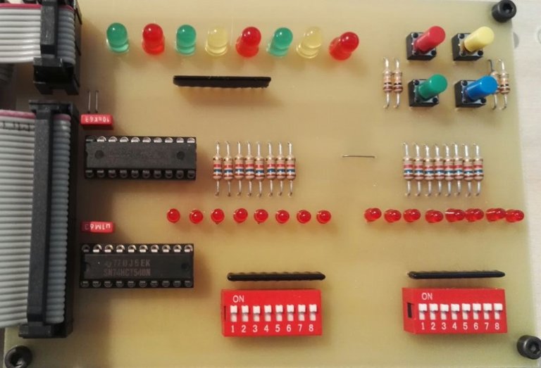
There are three times 8 LEDs, 4 push buttons and 2x8 DIP switches. Why always 8 LEDs and 8 DIP switches together. Because you can control one byte at a time (8 Bits) because it is a 8 Bit processor.
Programming
The processor is programmed with the software "keil" Website
The language is Assembler (it is difficult and not easy to understand)
Here is a little programm:
cseg at 0
mov P3, #255
mov P1, #255
main:
mov A, P3
rr A
rr A
mov P1, A
ljmp main
endThe first line says that the processor should start at the beginning of the memory.
The next two lines write the decimal value 255 -> 1111111 in binary into the port 1 and 3
Notice: This is a low active microprocessor (1 = low, 0 = high signal)
Now the two ports are completely off!
After that we set a jumppoint (main)
In main we now read from port 3 (the 4 buttons on the IO card) and write the value in the accumulator (1 Byte memory)
The processor can only do operations with values in the accumulator!
Now it gets tricky.
The value from the red button is: 1111011<- thats the value in the accumulator. If we know write this value to port 1 this LED lights up:
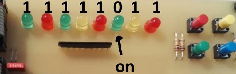
But we want the far right LED to light up when we press the red button.
Rotation!
with rr A we shift the byte one to the right:
11111011 -> 11111101
and another time:
11111101 -> 11111110
Now we can write to port 1
Because now the right LED lights up!
Just loop it!
after that the programm jumps back to main and the process starts over again.
Notice:
If you release the button the value is: 11111111 so the LED turns off!
Write the programm to the controller:
I am using the software AtmelISP and a USB to Serial converter to programm it.
Wow this is so cool! Did you use an AVR programmer for this?
Did something like that in school too it's sadly over and I did not do a lot of pictures.

I just found one of my internship hoped to find one of my micro controller which I used for my robot but did not do any pictures.
Wow that´s a lot of work. If you use your Atmel now in any real project (from automatic timer over water your flowers to electric door lock ) that could be subject in your next blogs
Thanks for your comment.
I would rather use an arduino because it is alot easier to programm. And the Atmel AT89S8253 has no analog to digital converter so potentiometers cant be used also it cant output pwm signals.
You are very limited, but it was fun to see how it works.
Writing in assembler is very hard and takes a lot of time
I have build something with an arduino. I will present it in another post :D