Tested on Kawasaki Ninja ZX6R
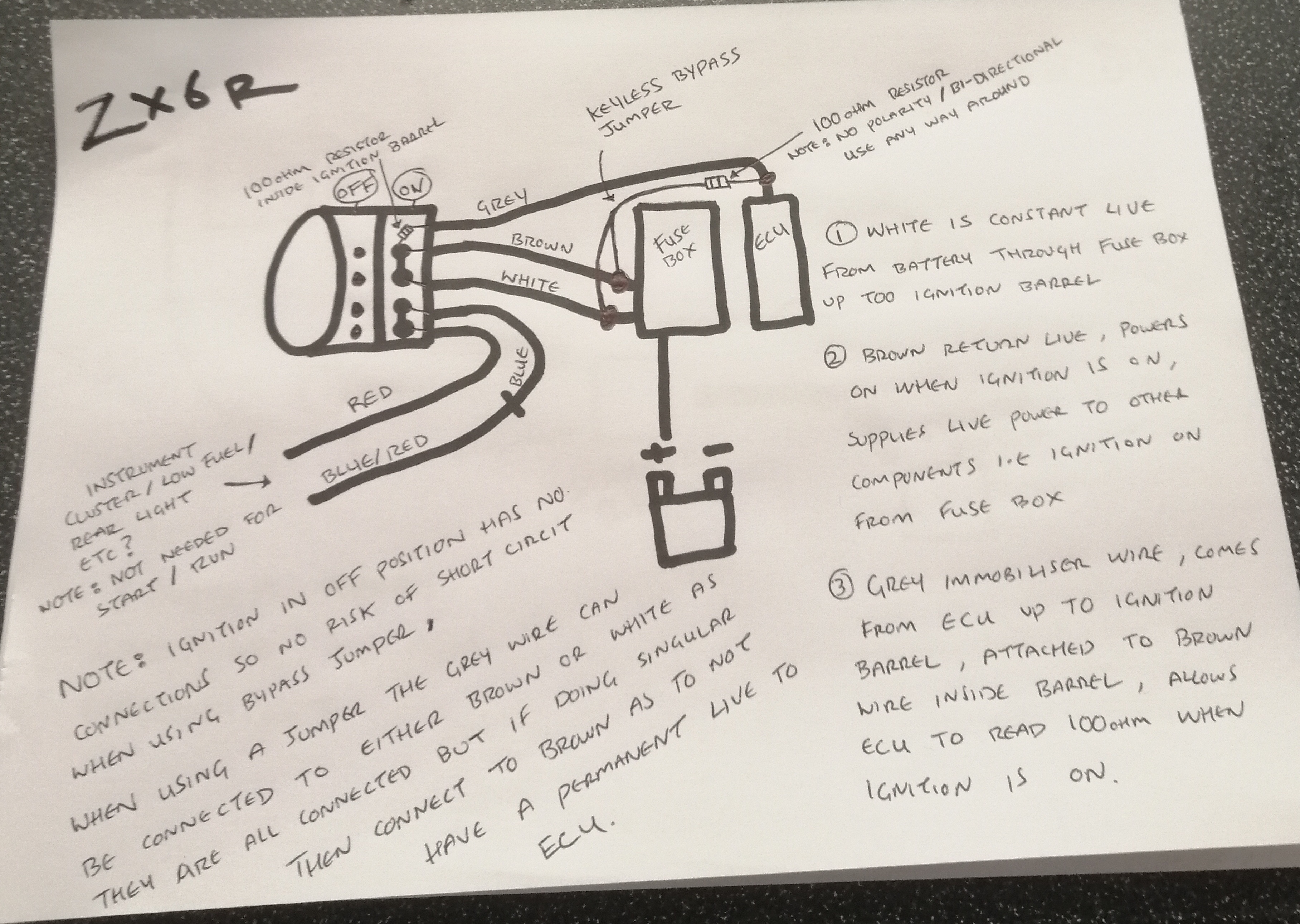
The goal of this modification was to convert the ignition system of a Kawasaki Ninja ZX6R to a keyless setup while bypassing the immobilizer, allowing the bike to start without using a traditional key. This was achieved by properly understanding the function of each wire in the ignition barrel and implementing a jumper with a 100-ohm resistor to satisfy the immobilizer requirements.
Background: Wiring and Components in the Ignition System
Ignition Barrel Wires
The ignition barrel of the Kawasaki Ninja ZX6R has five key wires, each with a specific role in the ignition and immobilizer systems. Here’s a breakdown of each wire:
White Wire - Live Power In:
- This wire connects directly to the battery, providing constant power to the ignition system.
- In the "On" position, this wire is typically connected to the brown wire, allowing power to flow to essential components.
Brown Wire - Switched Power Out:
- When the ignition is in the "On" position, the brown wire supplies power to essential circuits, such as the fuel pump and ignition coils.
- In this modified setup, the brown wire also connects to the grey wire (via the 100-ohm resistor) to simulate the immobilizer signal.
Grey Wire - Immobilizer Signal:
- This wire is part of the immobilizer system and communicates with the ECU.
- In the original ignition barrel setup, it connects to the brown wire through a 100-ohm resistor, creating the necessary resistance signal to allow the ECU to verify that the correct key is present.
Red Wire - Auxiliary Power (potentially for instruments or lights):
- Typically responsible for auxiliary power, this wire is energized in the "On" position, possibly powering the instrument panel or tail light.
Blue Wire - Fuel Pump/Instrument Signal:
- Likely involved in powering the fuel pump or sending a signal to the instrument cluster.
Immobilizer Bypass
In order for the ECU to recognize the ignition as being in the correct "On" position, it requires a 100-ohm resistance between the grey (immobilizer signal) and brown (switched power) wires. In a standard setup, this resistor is housed within the ignition barrel and is essential for allowing the ECU to authorize engine start-up.
Modification Steps
Materials Used
- 100-ohm Resistor (with 5% tolerance, indicated by a gold band)
- Jumper Wire
Procedure
Create the Resistor Jumper:
- A jumper was created by connecting a 100-ohm resistor inline with a short piece of wire.
- This jumper allows the grey wire from the ECU to connect to the brown wire while providing the required resistance for the immobilizer to recognize a valid key signal.
Connecting the Jumper:
- One end of the resistor jumper was connected to the grey wire coming from the ECU, and the other end was connected to the brown wire.
- This setup simulated the original resistor within the ignition barrel.
Completing the Ignition Circuit:
- Finally, the brown wire (now linked with the grey wire via the resistor) was connected to the white wire (live power in).
- This connection allowed the bike’s ignition system to power on, effectively bypassing the need for a physical key in the ignition barrel.
Results
Upon completing the connections, the motorcycle started successfully, demonstrating that the immobilizer had been effectively bypassed. The ECU read the correct 100-ohm resistance between the grey and brown wires, which it interpreted as a valid key signal. By connecting the brown and white wires, power was supplied to the essential circuits, enabling the bike to operate without a key.
Summary of Connections
- Grey Wire (ECU Immobilizer) -> 100-ohm Resistor -> Brown Wire (Switched Power Out)
- Brown Wire (connected to Grey via Resistor) -> White Wire (Live Power In)
Important Considerations- Non-Polarized Resistor: The 100-ohm resistor is non-polarized, meaning it can be connected in either direction between the grey and brown wires without affecting its function.
- Security Implications: Bypassing the immobilizer makes the motorcycle more vulnerable to unauthorized starts, as the original key verification is no longer required. Additional security measures, such as a hidden switch or secondary cutoff, may be advisable.
Conclusion
This modification enabled the Kawasaki Ninja ZX6R to operate with a keyless ignition setup while preserving the necessary immobilizer signal. By understanding the function of each wire and the role of the 100-ohm resistor, the immobilizer was effectively bypassed, allowing for successful engine start-up without a physical key.
This setup can now be reliably used in track environments or controlled scenarios where ease of ignition is prioritized over anti-theft security.


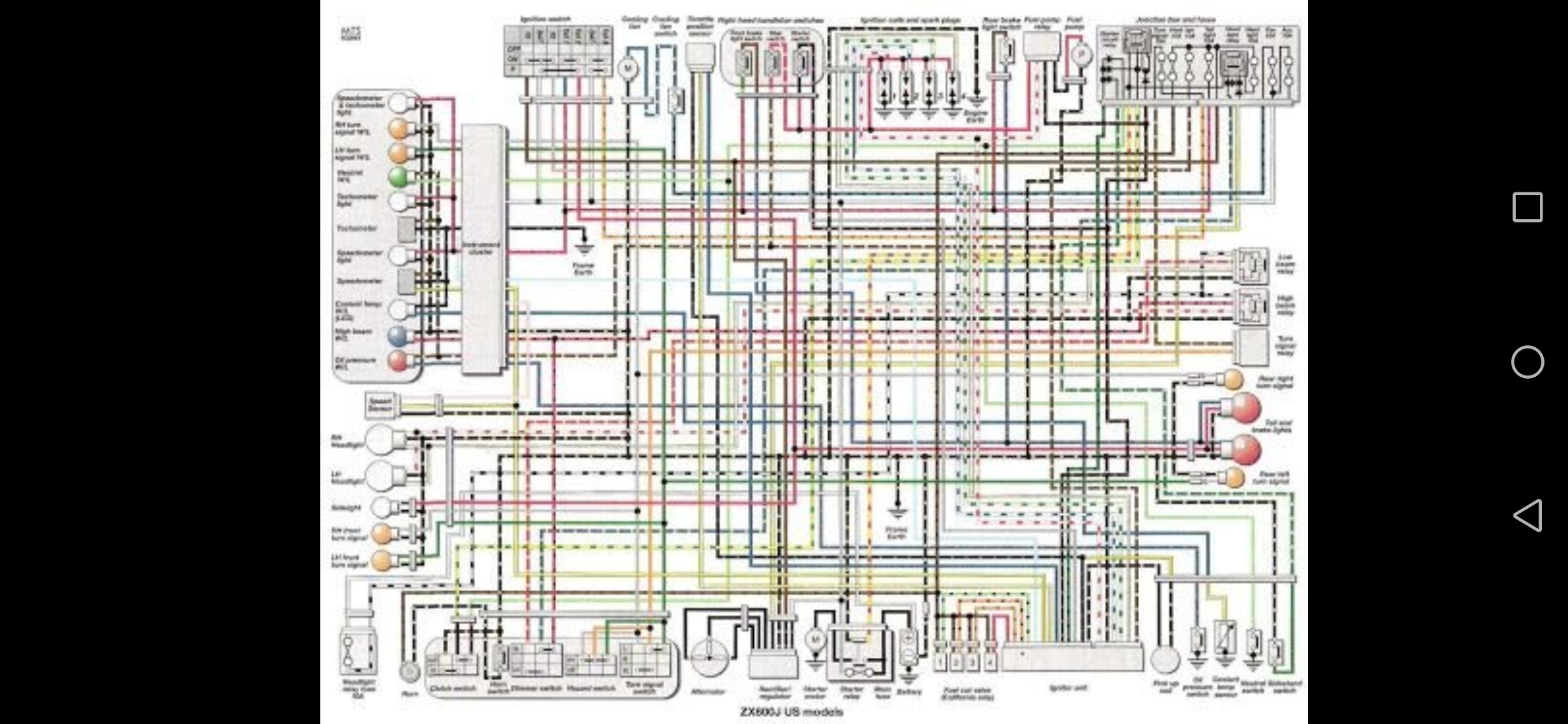
PLEASE NOTE:If anyone has a better copy of the wiring diagram please share link to were this can be found in comments below!-thankyou.Warning:
If ignition is locked in park position, other wires are connected, this could result in a short circuit,
Not tested so don't know what this would do,
Cutting all wires going directly to ignition barrel would prevent any issues and the keyless "key" could also be placed there. If this post gets enough likes, I'll share a photo of thes keyless key on the bike(target 5 likes)
I will be sharing the photo of the keyless key on the bike soon,thankyou.