Hello, guys. I intentionally didn’t write any articles on physics all these couple of days to fully observe what’s happening on the blockchain. I am very glad all is sorted now and we’ve forked away from Steem (now a centralized blockchain) into The Hive (a decentralized blockchain). It’s great to be on The Hive. I give kudos to each and everyone that partook and ensured the smooth transition. It’s a very nice transition and transformation. It’s like a new beginning for me on a new blockchain and I have done a brief re-introduction as such which you can check here.
So, outside the intro, I’ve resumed my normal blog writing. My article today is still on Imaging physics, picking up from where I stopped on Steem and trying to shine more light on the world of mirrors and telescopes.
So, grab a seat and tag along with me…….
Talking of mirrors
Plane mirrors are the most common optical devices we come across. The ordinary household mirror is a sheet of flat glass, ‘silvered’ on the back with a layer of metal paint (the metal is usually aluminium), which is then protected by a coat of ordinary paint. Light passes through the glass and is reflected by the silvering. A plane wavefront is reflected as a plane by a flat mirror, and the geometry results in the well-known rule: the angle of incidence equals the angle of reflection.
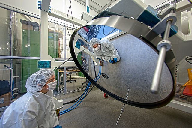
Deformable thin-shell mirror. It is 1120 millimetres across but just 2 millimetres thick, making it much thinner than most glass windows. ESO - http://www.eso.org/public/images/potw1307a/, CC BY 4.0
The angles are shown below and are measured from the normal line drawn at right angles to the surface.
As shown above, the image of an object reflected in a plane mirror is behind the mirror and as far from the mirror as the object is. Notice that light does not pass through the mirror, and the image is really an optical illusion. It isn’t really ‘there’ – you couldn’t, for example, catch it on a photographic film placed at the image position. The image is, therefore, a virtual image. Compare this image with the one produced by the lens which is formed from rays of light and can be caught on a photographic film. Our brain perceives (‘sees’) virtual images by making them into ‘real’ ones using another optical device – our eyes. An ordinary glass mirror produces a blurred image because of multiple reflections. Such a mirror is not suitable for optical instruments that need to give sharp images. There are two main solutions to this problem.
Front-silvered mirrors
These have the metallic layer on the front surface. Very fine metal particles are deposited on glass either from solution or from metal vapour in a vacuum. The large mirrors used in reflecting telescopes are made in this way. The metal surface is easily damaged, by touching or corrosion, and has to be treated with care.
REFLECTING PRISMS AND SNELL’S LAW
A glass (or clear plastic) reflecting prism provides a much cheaper more practical plane mirror by using the effect of total internal reflection,
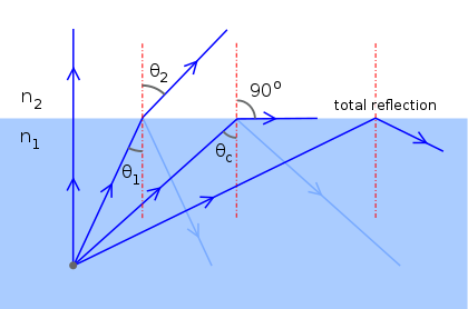
The figure below showed light rays which were partly internally reflected. It shows how total internal reflection occurs when the angle of incidence of a ray exceeds the critical angle c for the medium. When a ray reaches the inside of a plane boundary (say, between air and glass) at an angle of incidence greater than the critical angle, it cannot pass through the surface.
The relationship, given by Snell’s law, between the refractive index of a medium and its critical angle, is n = 1/sin c. The action of a prismatic mirror is shown. Such mirrors are used in some cameras and binoculars.
OPTICAL INSTRUMENTS: SINGLE-COMPONENT DEVICES
THE MAGNIFYING GLASS
A single converging lens can be used as a magnifying glass – sometimes called a simple microscope. The object is placed closer to the lens than the principal focus. The lens produces a magnified virtual image which is upright. The eyepiece lens of a (compound) microscope or a telescope may act as a magnifying glass in this way.
SPHERICAL MIRRORS
The concave mirror
A spherical mirror has much the same image-forming properties as a glass lens. The concave mirror focuses parallel rays to a point – its principal focus, F. To find the image of an object placed in front of a mirror, we can use the same kind of ray-drawing technique as for a lens.
Similarly, we can use the same formula relating object distance, image distance and focal length as we use for the lens, namely: 1/u + 1/v = 1/f.
A concave mirror can be compared with a positive (converging) lens, and can produce both real and virtual images. Concave mirrors are used as shaving and make-up mirrors in their virtual, magnifying mode. As with a lens used as a magnifying glass (see above), the object has to be nearer the mirror than the principal focus. Concave mirrors are also used as the objectives in large astronomical telescopes.
The simple geometry shows that the focal length f of the mirror is half the radius of curvature of the sphere of which the mirror is a section, so that PC = 2f. This focal length applies only if the angle made between the edges of the mirror and its sphere’s centre is very small, in other words, that the aperture of the mirror is small compared to its radius. Otherwise, we find that the image is blurred, a form of spherical aberration. Spherical aberration may be avoided for large mirrors by making the shape parabolic.
The convex mirror
Convex mirrors act like concave (diverging) lenses. Their focal lengths are negative and they form virtual images of real objects. They are used to give a wide field of view in car rear-view mirrors, in blind exits or entrances and as security mirrors in shops.
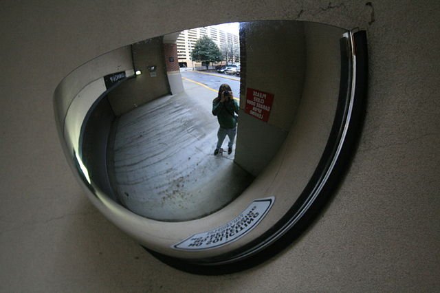
Convex mirror lets motorists see around a corner. Ildar Sagdejev, CC BY-SA 4.0
OPTICAL INSTRUMENTS WITH TWO COMPONENTS
THE ASTRONOMICAL REFRACTING TELESCOPE
An astronomical telescope is designed not only to magnify the apparent size of distant objects but also to gather as much light as possible. In the traditional refracting telescope which uses glass lenses, the light-gathering task is done by a large-aperture lens at the front of the instrument called the objective lens. The objective and eyepiece lenses work together to produce the magnified image.
The telescope shows the light rays from distant objects forming a ‘pencil’ of light that passes through the telescope. In optics, a distant object producing almost perfectly parallel rays (a plane wavefront) is said to be at infinity. The objective lens forms a real image of the object in the plane of its principal focus, F. The eyepiece is placed so that F is also at the position of the plane of its principal focus. Accordingly, the final pencil of light leaving the eyepiece and entering the eye is composed of parallel rays. The image is virtual, upside down (inverted) and also at infinity. The telescope set up like this is in normal adjustment, the usual arrangement for viewing distant objects. The position of the eyepiece can be altered to produce a real image, on a photographic plate, for example.
Magnifying power
It is observed that the emerging set of rays from the eyepiece of a telescope makes a larger angle, β, with the central axis of the telescope than angle α made by the incoming rays. So, imagine that we are studying a system of two stars, X and Y. Without the telescope, we would see the system as quite small. Suppose star X is at the centre of the picture. It sends light along the main axis of the telescope. Star Y is off-centre and sends light at angle α. When the light emerges from the telescope we see that Y appears to be further apart from X. In other words, the image of the system appears larger than with the naked eye. With a telescope, stars appear brighter and further apart, and we are able to see faint objects that were previously invisible.
The magnifying power of the telescope is simply the ratio of the image size seen with the telescope and the image size seen without it. The ratio is also the ratio (tan β/tan α) which, when the telescope is in normal adjustment, is also the ratio:
f0/fe
Where f0 is the focal length of the objective and fe is the focal length of the eyepiece.
The angles α and β are usually very small, so we can write (using radian)
Magnifying power = β/α = f0/fe
Defects of a refracting telescope
Refracting telescopes have their name because they use lenses, which refract light, to bring the light rays to a focus. It is hard to make large refracting astronomical telescopes because the large objective lens suffers from several kinds of aberrations. The most inconvenient of these is chromatic aberration. Rays of different colours are focused at different distances from the objective.
Also, as a lens has to be thick in the middle, a large aperture lens has a large mass, making it not only expensive but difficult to mount and control.
Galileo exploits the telescope’s potential
At the great annual fair at Frankfurt-am-Main in Germany in 1608, a wandering trader was offering a novelty for sale – a tube with a lens at each end, one concave and the other convex. When you looked through the tube, it magnified distant objects seven times. In October, a Dutch spectacle maker applied for a license to make and sell similar ‘telescopes’ (meaning ‘far seers’) but was refused because so many other people were already making them. By the following year, they were available for sale in London, Paris and Italy.
Galileo Galilei was then one of the most famous ‘natural philosophers’ in Europe – the word ‘scientist’ was not yet in use. Galileo is still revered as one of the greatest physicists of all time, but unlike some physicists, he was also smart. In August 1609 he went to his employers, the Senate of Venice, and offered them a device – a telescope – which would enable their trading fleets to see enemy ships long before the enemy could see them. The grateful senators immediately doubled his salary, just a few days before the local spectacle makers learned about telescopes and started making them for sale.
This kind of commercial smartness made the senators of the great trading Republic of Venice quite proud. A professor of physics and mathematics who could outsmart them was worth keeping, and they gave him a contract for life.
In fact, Galileo was (as far as we know) the first person to explain how the telescope worked. His improved design is named after him (while the man at the Frankfurt Fair was never known). The Galilean telescope uses a negative lens for an eyepiece, which means that the telescope can be shorter than the later and better – astronomical telescope, and it produces its image the right way up. The only place you are likely to see one is in theatres as the binoculars called ‘opera glasses’.
Galileo used his telescope to look at the mountains on the moon and the satellites of Jupiter. His observations convinced him that the old ideas of the nature of the Universe were wrong: the heavens were not ‘perfect’ – and the Sun was at the centre of a Copernican solar system of moving planets. It was these ideas that got him into trouble with the Catholic Church in Italy.
REFLECTING TELESCOPES
Some of the defects of refracting telescopes can be avoided by using a curved mirror as the objective, as in the Newtonian reflecting telescope. The mirrors in such telescopes do not suffer from chromatic aberration, and spherical aberration may be removed by making the shape slightly parabolic rather than perfectly spherical. Remember that the larger the aperture the more light can be collected and the better the resolution, as diffraction problems are reduced.
The objective mirror produces a real image of a distant object at its principal focus, F. This is usually offset by using a plane mirror so that the eyepiece can be mounted conveniently at the side, out of the way of incoming light. Apart from using a mirror as the prime focusing device, the reflecting telescope works just like a refracting type as far as size and magnification are concerned.
While one of the largest refracting telescopes has an objective lens 1 m in diameter, the Mauna Kea telescope in Hawaii has an objective mirror with an aperture of 10 m diameter. It is not easy to make large mirrors, but with the aid of computers several smaller mirrors can be made to combine images so that the effective aperture is increased. (The largest single-mirror telescope, at Zelenchukskaya, Russia, is 6 m in diameter.) Even larger apertures are now obtained by using adaptive optics and also by combining signals from widely spaced optical telescopes, with suitable time delays, to produce a higher-resolution signal. This technique has long been used with radio telescopes.
The Cassegrain telescope
We have seen that large magnifications require a long focal length. This means that the tube of a Newtonian telescope is inconveniently long, especially for amateur users. A Cassegrain system reduces the length considerably, as shown in the figure below. It uses a convex secondary mirror which extends the focal length, forming the image via a small hole in the main mirror. As it is technically much easier to make a spherical mirror than a parabolic one to the accuracy required, simple spherical mirrors are used with a glass correction plate. Its complex shape counteracts the defects of the mirrors.
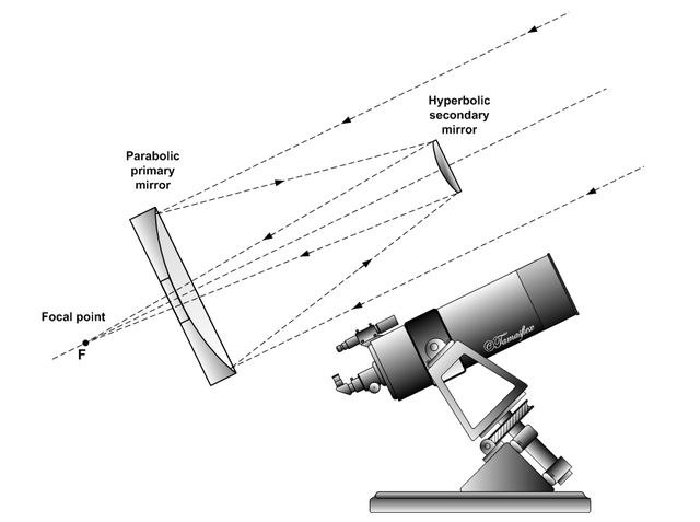
Light path in a Cassegrain reflecting telescope. Szőcs Tamás Tamasflex, CC BY-SA 3.0
THE COMPOUND MICROSCOPE
A compound microscope consists of two lenses, a lens combination that reduces aberration. It is designed to produce an enlarged virtual image of a small object. Light gathering is not as important as it is in a telescope, since the object can be brightly illuminated if necessary. The figure shows how a microscope forms its image.
The objective lens O forms a slightly magnified (intermediate) real image of the object at A. A is just inside the focal length of the eyepiece E, so that the final image I is virtual and highly magnified. It is usually arranged so that this final image is formed about 25 cm from the eye. This is the near point of the eye, where we normally place something that we want to see as large as possible.
Magnification in a compound microscope
The magnification produced by the compound microscope depends on where the final image is actually formed. The microscope is focused by moving the object closer to or away from the objective lens, a high power lens (with a small focal length).
We can find an approximate value for its magnification, which is good enough for everyday purposes, as follows. Assuming that the final image is 25 cm from the eyepiece, we can find an approximate value for the magnification Me produced by this lens. We can assume that the intermediate, real image is formed close to the principal focus f, of the eyepiece:
Magnification = Image distance from eyepiece/ Object distance from eyepiece
Me = 25/fe
The objective lens has a very small focal length. The object is placed close to the principal focus of the objective f0 and forms a real image close to the eyepiece, which also has a small focal length. So the image distance for the first image is almost the distance L between the lenses, and therefore roughly the length of the microscope tube. So, with measurements in centimetres, the magnification M0 produced by the objective is approximately:
M0 = L/f0
The total magnification of the compound microscope is, therefore:
M = M0Me = 25L/f0fe (measurements in cm)
BINOCULARS
Binoculars are a pair of telescopes, one for each eye. The magnifying optical principles are the same as in the astronomical telescope described above. The practical difference is that the tube is much shorter, and so the final image is upright.
Both these effects are produced by using reflecting prisms. The light travels along the tube three times so that the optical path is roughly three times the length of the binoculars. The prisms are arranged so that they invert the telescope image, which means it is finally the right way up.
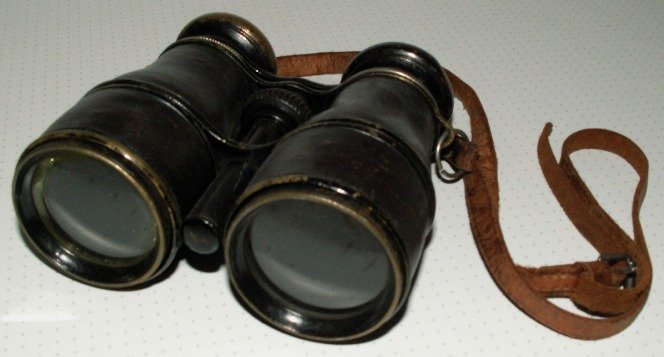
Galilean binoculars. ChiemseeMan, Public Domain
Thanks for reading.
REFERENCES
https://courses.lumenlearning.com/boundless-physics/chapter/mirrors/
https://www.brightstorm.com/science/physics/light/physics-mirrors/
https://en.wikipedia.org/wiki/Optical_instrument
https://www.slideshare.net/BivekTimalsina/component-of-optical-instrument
http://www.math.ubc.ca/~cass/courses/m309-03a/m309-projects/wong/pro.html
https://www.astronomynotes.com/telescop/s2.htm
https://www.jstor.org/stable/2901537
http://abyss.uoregon.edu/~js/glossary/reflecting_telescope.html
https://www.jstor.org/stable/232790
https://en.wikipedia.org/wiki/Reflecting_telescope
https://www.britannica.com/science/Cassegrain-reflector
https://en.wikipedia.org/wiki/Schmidt%E2%80%93Cassegrain_telescope
https://en.wikipedia.org/wiki/Cassegrain_reflector
https://en.wikipedia.org/wiki/Binoculars
https://en.wikipedia.org/wiki/Optical_microscope
https://www.britannica.com/technology/microscope/The-compound-microscope
https://www.microscopeworld.com/p-3470-what-is-a-compound-microscope.aspx
https://www.space.com/22505-worlds-largest-telescopes-explained-infographic.html
https://en.wikipedia.org/wiki/RATAN-600
If you appreciate the work we are doing, then consider supporting our witness @stem.witness. Additional witness support to the curie witness would be appreciated as well.
For additional information please join us on the SteemSTEM discord and to get to know the rest of the community!
Thanks for having used the stem.openhive.network app. This granted you a stronger support from SteemSTEM. Note that including @steemstem in the list of beneficiaries of this post could have yielded an even more important support.