The basis of Electric energy systems engineering is reliant on the knowledge that it is possible to transform the crude energy forms endowed by nature into electric energy. And it is also possible to transform the raw energy forms bestowed by nature into electrical energy; and that it is also possible to transmit this electrical energy down to the potential user irrespective of distance and ultimately transform it back into useful energy forms of different types.
.png)
This energy transformation takes place in a kind of cycle or roundabout fashion which we can easily understand by considering energy derivable from the chemical energy of coal. The pulverised coal is mixed with air in the combustion chamber of the boiler where it burns to release enough energy capable of raising steam from boiling water.
In a series of heat exchangers, the thermal energy is transmitted to another medium, water, which absorbs the thermal energy and consequently turns to steam. The steam is channelled through to the turbine where it gives off some of its thermal energy after expanding in the turbine and doing some useful work. The turbine converts the thermal energy into mechanical energy. Finally, in the alternator, the mechanical energy is transformed into electrical energy.
Going through the above steps involved in the energy conversion process, you will notice that the energy transformation involves the loss of energy which is quite significant at different stages of the process. This energy loss is not surprising as the efficiency of conventional steam turbine power plant is just 29% owing to the heavy losses in the flue gases, condensers, ashes, etc.
In practice, close to 95% of the electric energy that is produced today is derived from rotating generators, which involves at the last stages the energy transformation step of mechanical to electrical.
There is the drive through intensive research to adopt the direct energy conversion DEC methods. The striking difference between the direct energy conversion methods eliminates forever the need for intermediate mechanical energy step which involves the prime mover and the generator shaft in the generation of electrical power.
This method seeks to obtain electrical energy directly from either thermal, solar or chemical form. There are different forms of DEC methods, but they are not so popular given that they are only economical for low power application.
The DEC that will be discussed in this article include thermionic, thermoelectric, fuel cells and MHD.
Thermionic Emission
Thermionic emission involves the release of electrons from heated materials which is highly exploited as a source of electrons in the television picture tubes in the field of electronics and communications.
Heat is necessary for thermionic emission, to supply the electron the minimal energy needed to counteract the attractive forces securing them in the structure of the metal. The energy needed to break away from the attractive forces holding the electrons within the lattice structure is known as minimal energy, and it is often referred to as the work function, and this is particular to the emitting material and the level of contamination of its surface.
)
A thermionic power converter can be seen as electronic diode capable of converting heat energy into electrical energy through thermionic emission. Regarding thermodynamics, it can be likened to a heat engine that makes use of the gas containing ample quantity of electrons as its working fluid.
The major setback working against the development of practical thermionic converters is the limit placed on the maximum current density due to space charge effect. It is worthy to mention that the space charge effect is as a result of the inability of the electrons emitted by the cathode to hit the anode instantaneously.
This time lag involved in the electron movement from the cathode to the anode leads to accumulation of negative charge which forms a cloud of electrons in the space within the anode and the cathode.
There are two ways in which this problem of space charge can be reduced. One entails lessening the distance between the two electrodes to the order of micrometres, while the other involves introducing the positive ions into the cloud for possible recombination. The latter proposition has worked better and is more feasible from many considerations, especially in the aspect of manufacturing.
Emission of electrons is the basis of thermionic power conversion. The energy needed to knock out an electron from the surface of an emitter is known as the electronic work function. Some electrons within the surface of the emitter may have energy higher than the work function and as such will break away on their own in the absence of excitation.
Worthy to remember is the fact that the rate of emission of electrons increases at a faster rate with increase in emitter temperature and drops exponentially with the work function.
This behaviour goes to explain why it is preferable to choose a material that has a small work function but can operate with high reliability at a higher temperature over one that is unpredictable as the temperature increases.
Excess kinetic energy is impacted on the electron that leaves the emitter surface, and the energy gained by these electrons is equivalent to the work function of the said material.
When the electron strikes the collector, a part of the energy is used to force current to flow through the external load, and as such, the desired conversion is completed directly from the thermal to electrical energy.
The energy conversion is not 100%, and part of it is converted to heat which requires that we must provide a means to evacuate the heat to maintain the collector at the suitably low temperature.
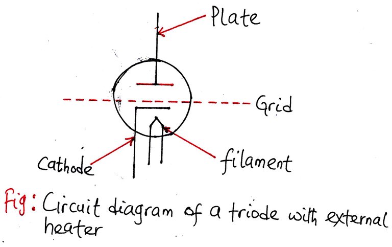
The thermionic valves (vacuum tubes) is composed of the following components:
- The cathode (K)
- Anode (P), also known as the plate
- Control Grid (G)
- Filament (F), sometimes called the heater
The thermal energy may be gotten from chemical, solar or nuclear sources. The thermionic converter operates with no moving parts and can be designed to exhibit high reliability coupled with long service life. For this reason, thermionic devices can find favour in spacecraft applications.
Thermoelectricity
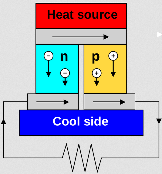
Thermoelectricity involves the direct conversion of heat into electricity or vice versa. The principle is quite simple. When two metals are placed in electrical contact, there will result in an electron flow from the material having a higher Fermi level to the one having a lower Fermi level. Fermi level is energy state of an electron as a result of half-filled orbitals.
.png)
The study of electronic configurations of most materials revealed that element with incomplete electrons in their subshell tends to acquire sufficient energy to leave the parent atom as they are loosely bound. This phenomenon is exploited here when two metals having different Fermi level are placed in electrical contact; this results in a flow of electrons from the electrons loosely bound to its parent atom into the other one.
This movement of electrons pushes up the lower Fermi level and lowers the higher fermi level. This transfer of electrons continues until the Fermi levels of the two materials become equal.
For there to be a current flow, there has to be a temperature difference between the two of the junctions. This difference in temperature involves raising the temperature of one of the intersections and lowering the temperature of the other.
)
This temperature difference is ensured by making sure that the heat enters the hot junction and leaves through the cold junction. This thermal electromotive force at a junction is referred to as Seebeck effect. The metals must be dissimilar so that they will possess different Fermi level with unidentical temperature dependence. The popular materials for thermocouples are iron and constantan.
This phenomenon is applied to the measurement of temperature with high sensitivity and accuracy and to generate electric power for a specific application.
Thermocouple Output Voltage
In reality, to tap useful current from the ends of a conducting rod needs the connection of wires to the end-points. This connection will introduce a second conductor in parallel between the heat source and the heat sink. The voltage generated in the wire connected to extract the power will create an opposition voltage generated across the rod with the effect that the net generated voltage will now be the difference between the voltages generated across the rod and that of the voltage across the wires.
)
The thermoelectric voltage generated in the in a single conductor is quite small, and the best efficiencies are in spacecraft applications with the efficiency of up to 8%.
In practice, the thermocouple applications are limited to low power devices as there are more efficient ways of turning heat into electricity.
Higher efficiencies can be achieved at the expense of utilizing more heat by increasing the temperature differences between the hot and the cold surfaces.
It is mostly applied in temperature measurement, also to detect the direction in bolometers, and heat sensing.
Thermopile
Since the energy derivable from a single thermocouple is small, a cascade of thermocouples must be employed to form an array of thermocouples. By connecting the thermocouple in series, it is possible to generate a reasonable amount of power from the thermopile.
Fuel Cells
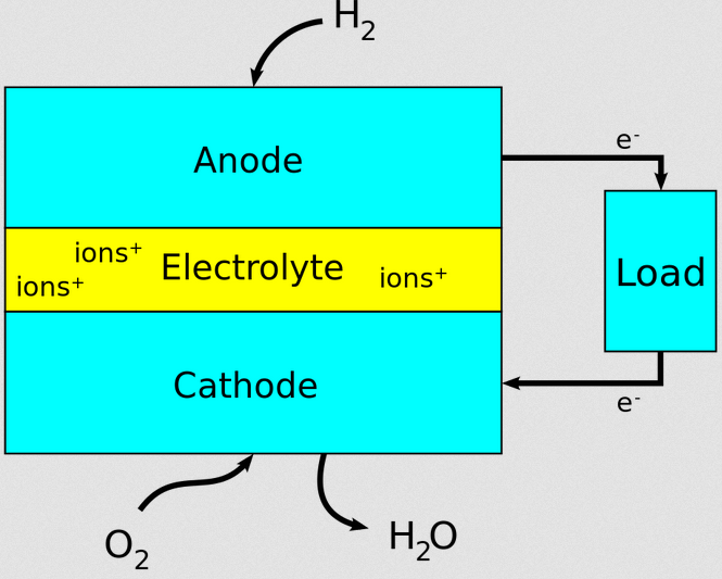
The fuel cell is an electromechanical energy conversion device that is capable of generating electrical energy quite efficiently and quietly. A fuel cell utilises the chemical energy inherent in hydrogen and oxygen and in the process of converting this chemical energy into water, electricity is generated.
One may wonder if the electrochemical device such as the battery is the same with the fuel cells but in essence, it is entirely different in that battery has all its chemical energy stored inside of it which it converts into electricity in like manner as in fuel cells. The difference between the two lies in the fact that battery will eventually discharge and go dead which can still be restored by charging.
)
But when it comes to the fuel cell, the energy derivable is constant as long as there is a fresh flow of chemicals into the cell. A higher percentage of fuel cell available today use hydrogen and oxygen as raw material for subsequent conversion to electricity through a chemical reaction.
A fuel cell consists of two electrodes called the anode and the cathode. There is also in it, the electrolyte, with the responsibility of transporting charged particles from one electrode to the other. It is often impregnated with a catalyst for speeding up the reactions at the electrodes.
You may have been wondering why fuel cells are getting such massive attention from government, academic institutions and even private enterprises.
The reason is not far-fetched when you consider the fact that it generates electricity with minimal pollution.
Since a single fuel cell is incapable of generating a significant amount of electricity, it is a common practice to assemble many fuel cells into a stack.
There are different types of fuel cells, but the operating principle remains the same. The hydrogen atoms enter the fuel cell through the anode and utilising chemical reaction it relinquishes its electrons. In the process of losing its electrons, the hydrogen atom becomes ionised and bears a positive electrical charge.
The electrons which are negatively charged can be tapped off to do useful work using wires.
The output of the fuel cell is DC but in that AC is needed, the DC output of the fuel cells must be directed to the inverter for conversion from DC to AC.
The oxygen is introduced into the fuel cell through the cathode where it picks up electrons and then moves through the electrolyte to the anode for possible recombination with hydrogen ions.
The electrolyte plays a vital role in checkmating what passes between the anode and the cathode. In other words, it must allow only the appropriate ions to transit between the electrodes. This selection is necessary because if free electrons or other substances were to be allowed to travel through the electrolyte, they would interfere with the chemical reaction.
Irrespective of where the recombination takes place (anode or cathode), together with hydrogen and oxygen to form water, which depletes the cell. As long as there is a constant supply of hydrogen and oxygen, it will continue to generate electricity.
MHD Generators
In MHD, the M stands for Magnetic field and H is for Hydro (flowing fluid) and D for Dynamics. The conducting media consists of very hot ionised gases (plasma) having negatively charged electrons and positively charged ions.
These are flown through MHD tunnel or channel at very high (supersonic) velocity (U). Strong unidirectional magnetic field (B) is applied in the direction perpendicular to the direction of the velocity of the plasma. The conducting particles in the plasma experience a force (E) in the direction mutually perpendicular to the direction of magnetic field and the direction of velocity (flow).

Thus the charged particles in plasma move in the direction of this force (E) in a perpendicular direction to the magnetic field (B) and direction of the original velocity (U) of plasma.
According to the electromagnetic field theory, the charged particles will experience a force in the direction of the electrical field. Thus the interaction between the plasma at velocity (U) and magnetic field of flux density B produces electrical field (E) such that E, U, B are mutually perpendicular.
The principle of MHD power generation is based on Faraday’s law of electromagnetic induction which has it that when there is a relative motion between a conductor and a magnetic field, there will be an induced voltage in the conductor, which causes a current to flow across the terminals.
)
As we can easily guess from the name, the magnetohydrodynamic generation involves the flow of a conducting plasma in the presence of magnetic and electric fields. The conventional generator consists of the conductor in the form of copper windings, but in an MHD generator, the hot ionised gas or conducting plasma replaces the solid conductor.
The plasma at high pressure is composed of electrically conducting fluid flows through a transverse magnetic field in an MHD channel or duct. A Pair of an electrode is made available on the channel walls at 900 to the magnetic field and connected through an external circuit to supply power to a load connected to it. These electrodes in the MHD generator is the counterpart of brushes in a conventional DC generator.
In vector form, we get
E = U × B
B = magnetic field vectors in wb/m2 or Tesla
In summary, when charged particles flowing in direction U are subjected to strong magnetic field vector B, an electrical field vector E is generated in the direction perpendicular to U and B such that
E = U × B
Electrodes placed at a distance d across the electric field develop a dc voltage
V = E× d volts
where V= voltage
E = Electric field strength
d = distance between the two electrodes
When they are connected to an external circuit, DC power flows through the external circuit and can be converted to AC with the help inverters.
P = V× I Watts.
Conclusion
Direct energy conversion is getting popular by the day due to its inherent compact nature and ability to fit in in a small space as compared to generators that make use of turbine which drives the alternator. This method of generation negates the use of generator shaft and converts thermal energy directly to electricity.
Fortunately, the heat recuperated from exhaust gases of gas turbine plant can be used to add heat to MHD plasma before propelling it to a supersonic speed. This heat extraction from exhaust and flue gases will improve the combined efficiency of both plants.
The compact and modular nature lends it to the application in remote areas terrestrial and spaceship application where space is premium.
Research is ongoing to improve its efficiency for bulk power generation.
Being A SteemStem Member
As I was reading your post, it just occurred to me that all we do in the field of Electrical Engineering (and the whole of engineering) is to convert energy from one form to another where it suits our needs. I think it is rather fortunate for us as humans that the law of conservation of energy is exactly how it is or else, we would have either put ourselves into trouble with the energy we produce or we would have had no energy to help us achieve the civilization which places us above other animals.
Your post is as organized as always. One day, one may just visit your page whenever there is need to learn power systems. Thanks for sharing.
Many thanks for always making out time to read my posts. I really appreciate your input and your knack to capture the essence of my posts.
Congratulations! Your post has been selected as a daily Steemit truffle! It is listed on rank 5 of all contributions awarded today. You can find the TOP DAILY TRUFFLE PICKS HERE.
I upvoted your contribution because to my mind your post is at least 24 SBD worth and should receive 98 votes. It's now up to the lovely Steemit community to make this come true.
I am
TrufflePig, an Artificial Intelligence Bot that helps minnows and content curators using Machine Learning. If you are curious how I select content, you can find an explanation here!Have a nice day and sincerely yours,

TrufflePigThanks a lot for deeming my post interesting.