In order for something happen a computer need some kind input and output. For 65C02 the best choice of I/O is the 65C22 VIA (Versatile-Interface-Adapter). It offers parallel, serial I/O, timer and IRQ management.
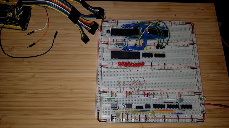
Add 65C22 VIA and most of it's control lines
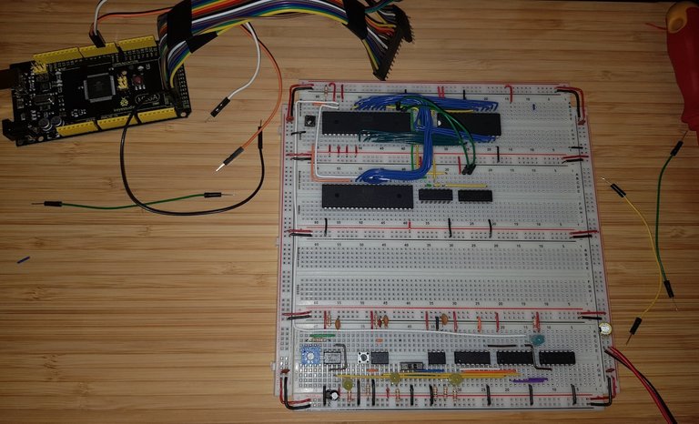
Compared to the video you might notice the 2ⁿᵈ integrated circuit. This is the 74LS21 2×4 AND gates. Ben Eater has reserved 8kb of memory for the VIA. I think that's a bit much as the VIA only needs 16 bytes. I have decided to do the project in hard mode and try to get the VIA memory usage below one page (256 bytes). That's the what both the Atari 800 and C64 used for there I/O chips.
Add the 4 register select lines and the first two LED
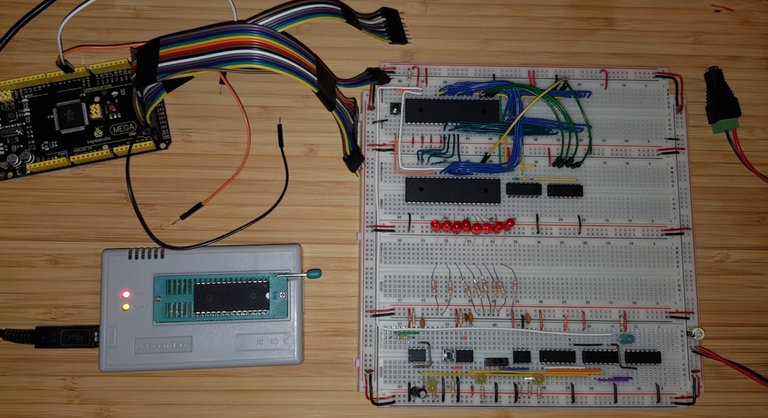
Write the new LED blink program to the ROM
The new Ada program to generate ROM image with an program that makes the LED blink:
with Ada.Sequential_IO;
with Ada.IO_Exceptions;
with Ada.Command_Line;
with Ada.Text_IO;
with Interfaces;

procedure Create_LED is

   type Byte is new Interfaces.Unsigned_8;
   type Address is new Interfaces.Unsigned_16;

  --  One of the cool feature of Ada is it's ability to set the lower and
  --  upper bound of an array to any value you want. So we can set use the
  --  actual ROM addresses as array index an save ourself the work and
  --  remove one potential error source.
  --
   type ROM_Type is
      array (Address range 16#8000# .. 16#FFFF#)
      of Byte;

   package ROM_IO is new Ada.Sequential_IO (ROM_Type);

   ROM_Output : ROM_IO.File_Type;

  --  65C02 related constants as named in the original
  --  WDC design document
  --
   NOP  : constant Byte    := 16#EA#;
   NMIB : constant Address := 16#FFFA#;
   RESB : constant Address := 16#FFFC#;
   IRQB : constant Address := 16#FFFE#;

  --  Another interesting feature Ada arrays is specifying the index of
  --  elements when initialising the array. As well specifying an value
  --  for all not explicitly initialised values. Makes setting up the
  --  ROM array super easy.
  --
   ROM : constant ROM_Type :=
      (16#8000# => 16#A9#,  --  LDA #$FF
       16#8001# => 16#FF#,
       16#8002# => 16#8D#,  --  STA $7F02
       16#8003# => 16#02#,
       16#8004# => 16#7F#,
       16#8005# => 16#A9#,  --  LDA #$55
       16#8006# => 16#55#,
       16#8007# => 16#8D#,  --  STA $7F00
       16#8008# => 16#00#,
       16#8009# => 16#7F#,
       16#800A# => 16#A9#,  --  LDA #$AA
       16#800B# => 16#AA#,
       16#800C# => 16#8D#,  --  STA $7F00
       16#800D# => 16#00#,
       16#800E# => 16#7F#,
       16#800F# => 16#4C#,  --  JMP $8005
       16#8010# => 16#05#,
       16#8011# => 16#80#,
       NMIB + 0 => 16#00#,  --  .word $8000
       NMIB + 1 => 16#80#,
       RESB + 0 => 16#00#,  --  .word $8000
       RESB + 1 => 16#80#,
       IRQB + 0 => 16#00#,  --  .word $8000
       IRQB + 1 => 16#80#,
       others   => NOP);

begin
   if Ada.Command_Line.Argument_Count < 1 then
      Ada.Text_IO.Put_Line ("Syntax: Create_LED <output file>");
   else
      declare
         File_Name : constant String := Ada.Command_Line.Argument (1);
      begin
         ROM_IO.Create (ROM_Output, ROM_IO.Out_File, File_Name);
      exception
         when Ada.IO_Exceptions.Name_Error =>
            Ada.Text_IO.Put_Line ("File “" & File_Name & "” couldn't be created.");
            Ada.Text_IO.Put_Line ("See stack trace below for more details.");
            raise;
      end;

     --  Just like Python Ada can write the whole array in one go.
     --
      ROM_IO.Write (ROM_Output, ROM);
      ROM_IO.Close (ROM_Output);
   end if;
end Create_LED;
You might noticed that I have added a white marker to the EEPROM. At one time I plugged the ROM in reverse which gave a new meaning to “smoke test”. The EEPROM got hot enough to start smelling. Luckily the EEPROM survived.
Everything black
And nothing happens. I guess I need to add the Arduino for debugging. Since memory management and the generation of the of the chip select signals are the most likely reason I updated the Monitor program to show the status of the two chip select signals.
#include <USBAPI.h>

/**
 * Bus class handles reading the 6502 address and data bus
 */
class Bus
{
private:
    /**
     * Size of the 6502 bus (16 for address bus and 8 for data bus).
     */
    size_t const Size;
    /**
     * Arduino I/O lines the 6502 bus is connected to.
     */
    byte const* Lines;

public:
    /**
     * initialise Bus.
     *
     * @param Size of the 6502 bus (16 for address bus and 8 for data bus).
     * @param Arduino I/O lines the 6502 bus is connected to.
     */
    Bus (const byte Lines[], size_t Size) :
        Size (Size),
        Lines (Lines)
    {
    } // Bus

    /**
     * initialize the Arduino I/O lines used to monitor the 6502 bus to INPUT.
     */
    void Init () const
    {
        for (size_t i = 0;
             i < Size;
             i++)
        {
            pinMode (Lines[i], INPUT);
        } // for

        return;
    } // Init

    /**
     * read the but date from the Arduino I/O lines.
     *
     * @return value read.
     */
    word Read () const
    {
        word Retval = 0;

        for (size_t i = 0;
             i < Size;
             i++)
        {
            auto bit = digitalRead (Lines[i]) == HIGH ? 1 : 0;

            Serial.print (bit);

            Retval = (Retval << 1) + bit;
        } // for

        Serial.print (" ");

        return Retval;
    } // Read
};

/**
 * Address bus
 */
static Bus const A = Bus (
    (byte[16]) {22, 24, 26, 28, 30, 32, 34, 36, 38, 40, 42, 44, 46, 48, 50, 52},
    16);

/**
 * Data bus
 */
static Bus const D = Bus (
    (byte[8]) {39, 41, 43, 45, 47, 49, 51, 53},
    8);

/**
 * Clock pin
 */
static byte const PHI2 = 2;

/**
 * executed at every clock pulse of the monitored 6502
 */
static void On_Clock ();

/**
 * VIA read/write pin. (read high, write low)
 */
static byte const RWB = 3;

/**
 * VIA Chip select one pin. (active high)
 */
static byte const CS1 = 4;

/**
 * VIA chip select two pin. (active low)
 */
static byte const CS2B = 5;

/**
 * Setup Arduino
 */
extern void setup ()
{
    Serial.begin (115200);
    Serial.println ();
    Serial.println ("Start 6502 Monitor");

    // Setup address bus pins
    //
    A.Init ();

    // Setup data bus pins
    //
    D.Init ();

    // Setup clock pin
    //
    pinMode (PHI2, INPUT);
    attachInterrupt (digitalPinToInterrupt (PHI2), On_Clock, RISING);

    // Setup read/write pin
    //
    pinMode (RWB, INPUT);

    return;
} // setup

extern void loop ()
{
    // do nothing

    return;
} // loop

/**
 * executed at every clock pulse of the monitored 6502
 */
static void On_Clock ()
{
    auto Address = A.Read ();
    auto Data = D.Read ();
    auto Read_Write    = digitalRead (RWB)  == HIGH ? 'r' : 'W';
    auto Chip_Enable_1 = digitalRead (CS1)  == HIGH ? 'E' : 'd';
    auto Chip_Enable_2 = digitalRead (CS2B) == LOW  ? 'E' : 'd';
    char Output[15];

    snprintf (
      Output,
      sizeof Output,
      "%04x %c %c %c %02x",
      Address,
      Read_Write,
      Chip_Enable_1,
      Chip_Enable_2,
      Data);
    Serial.println (Output);

    return;
} // On_Clock

Testing with reduced memory management
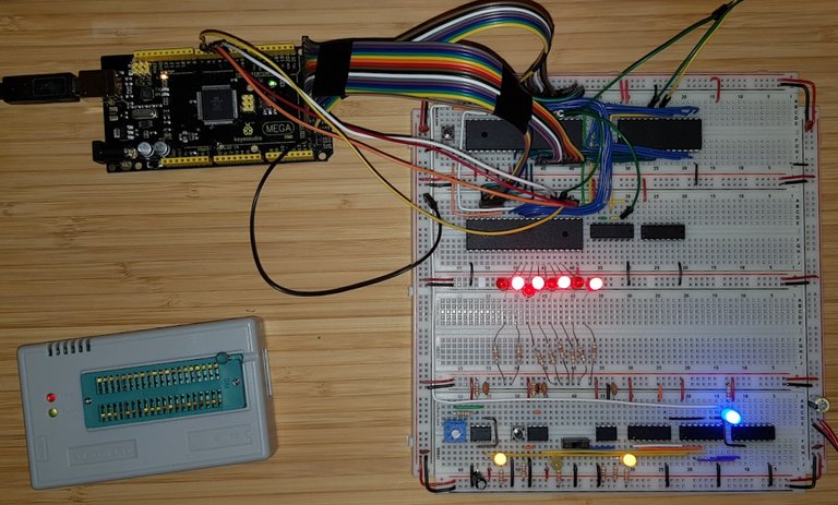
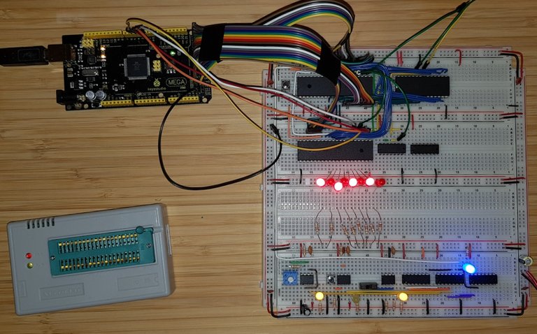
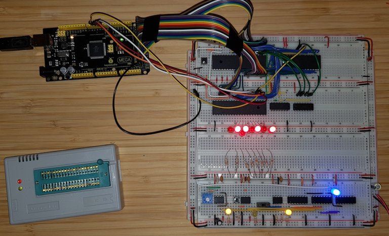
It blinks
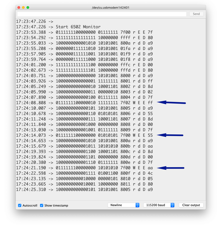
Monitor output
The problem was that the VIA, unlike the CPU needs an explicit reset signal. Everything else was fine.
Test again with more elaborate memory management
Still blinks
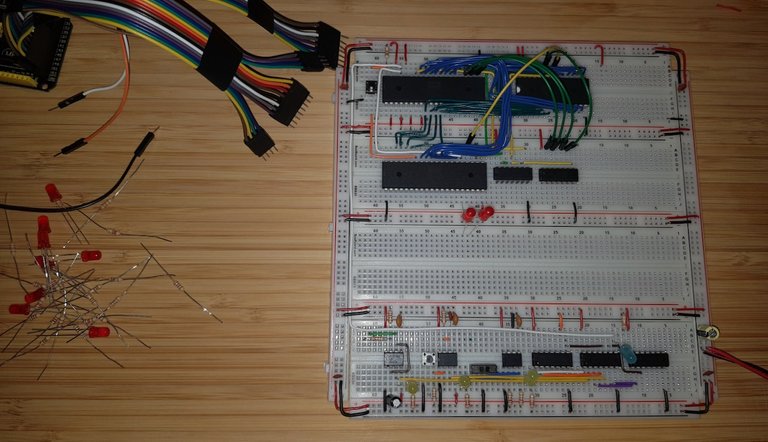
Currently memory usage for the VIA is down to 2kb as only half the 74LS21 is used. I'll start using the full 74LS21 once the RAM has been added to the system. For now the the chip is only wired up temporarily with jumper wire.
You find the source code for the ROM creation program with makefile, project file and source code on GitLab: 6502Tutorial — Tools/Create_LED
You can find the extended Monitor program on GitLab: 6502Tutorial — Tools/Create_LED
Congratulations @krischik! You have completed the following achievement on the Hive blockchain and have been rewarded with new badge(s) :
You can view your badges on your board and compare yourself to others in the Ranking
If you no longer want to receive notifications, reply to this comment with the word
STOPDo not miss the last post from @hivebuzz: