1. Introduction
(Time-dependent) A double acting cylinder is used to press together glued components. Upon operation of a push button, the clamping cylinder slowly advances. Once the fully extended position is reached, the cylinder is to remain for a time of T = 6 seconds and then immediately retract to the initial position. A new cycle is only possible after the cylinder has fully retracted after 5 seconds. During the delay the finished part is manually removed and replaced with a new parts for gluing. The retracting speed should be fast, but adjustable.
(Pressure-dependent) A plastic component is embossed using a die powered by a double-acting cylinder. The return of the die is to be affected when the cylinder rod has fully extended to the embossing position and the preset pressure is reached. A valve with roller and limit switch is used to confirm full extension. The signal for retracting must only be generated when the piston rod has reached the embossing position. The pressure in the piston chamber is indicated by a pressure gauge.
2. Method and Simulations
2.1 Time-dependent control
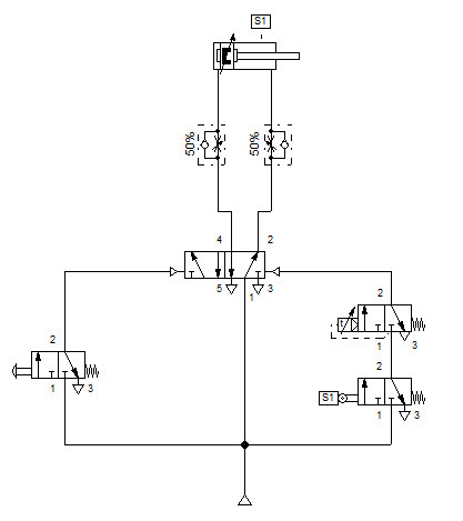
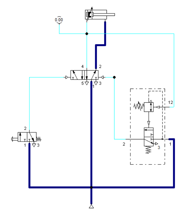
The time-dependent control utilizes a normally open pneumatic timer for the retraction of the double acting cylinder, as shown in Figure 2. The circuit was built in reference to the indirect control except for the integration of a pneumatic timer and sensors. In general, it is composed of :
a compressed air supply which supplies the air that will be used as an actuating medium to the whole circuit;
a 3/2-way valve actuated by a push button that simulates as a switch to activate the circuit;
a 3/2-way valve that is mechanically actuated that detects if the piston has reached its maximum
extension capacity.a 5/2-way valve that is pneumatically actuated which is responsible for letting the air flow to the cylinder in both extending and retracting action;
A flow control valve that regulates the air to control the speed of the piston when it extends;
a pneumatic timer that restricts the air flow to the bottom of the piston for 6 second; and,
double acting cylinder that actuates in accordance to the scenario.
When the push button is pressed, the air flows through the 5/2-way directional valve that causes the cylinder to extend. The speed of extending the piston rod of the cylinder is controlled by the one-way control valve which is in between the 5/2 way DCV and the double-acting cylinder. and which will also allow the air to flow through it.
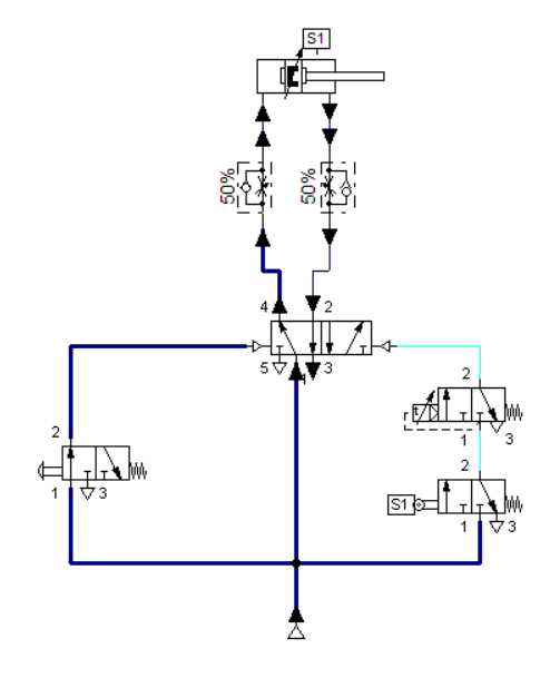
Once the piston reaches the sensor S1 and is fully extended, the 3/2-way directional control valve with limit switch (S1) actuates the pneumatic timer. After t = 6 sec, the control valve at the timer opens to actuates the port 15 of the 5/2 way directional control valve. Once port 15 is actuated, the valve opening shifts from port 4 to port 2. This causes an air flow across the retraction port of the cylinder.

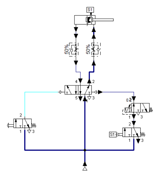
2.2 Pressure-dependent control
In the initial position, the port 3 of the 5/2 way directional valve is normally open and air pressure is applied to the retraction port of the cylinder, as shown in Figure 2. When the push button is actuated, the 5/2 way directional control valve shifted the opening from port 2 to port 4. It extends the cylinder as shown in Figure 3.
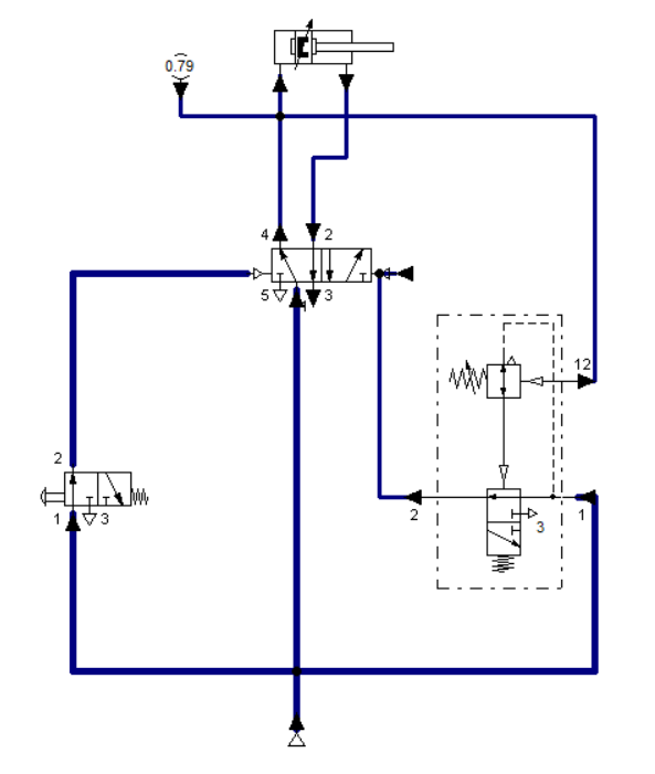
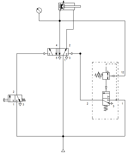
The cylinder retracts once the set pressure value in the pressure valve is achieved. This configuration are commonly employed with system that needs a specific pressure limits to operate. For example, when embossing a plastic mold, the emboss needs to be applied with a specific pressure to achieve a quality embossing on the material or surface. The pressure gauge measure the pressure across the port 14 of the 5/2 way DCV. This measure is feed to the port 12 of the pressure valve. This measured value is compared to the reference value at the valve.
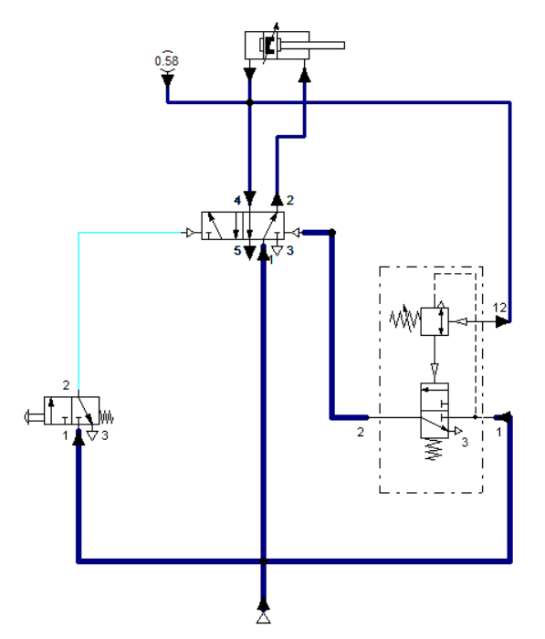
When the pressure reaches the value set at the control port of the pressure sequence valve, the 3/2-way valve of the pressure sequence valve activates. The 5/2 way DCV shifted from port 4 to port 2 and it causes the piston rod retracts. During the retracting movement, the limit switch in the pressure valve is released. The signal at the control port of the 5/2 way DCV reset as well as the pressure sequence valve.
3. Conclusion
Time delay valve is a combination of a pneumatically actuated 3/2 way direction control valve, an air accumulator and one-way flow control valve. The time delay function allows controlling the air's rate of flow to or from the reservoir by means of a throttle valve. Adjustment of throttle valve permits fine control of time delay between minimum and maximum times. In pneumatic, time-delay valves ranges between 5 to 30 seconds. On the other hand, pressure sequence valve transmit a pneumatic signal once the reference or set pressure value is achieved. It's output signal is used to control the cylinder action by setting or resetting a signal through the final control valve (5/2 way DCV).
4. References
[1] Pneumatic Basic Level. online access
[2] Pneumatic Advanced Level. online access
(Note: All images and diagram in the text are drawn by the author (@juecoree) except those with separate citation.)
If your are Interested in Pneumatic Basics, you can read the other posting:
1. Pneumatic Basics: Direct Control
2. Pneumatic Basics: Indirect Control
3. Pneumatic Basics: AND and OR Logic
4. Pneumatic Basics: Memory Circuit and Speed Control
Posted with STEMGeeks