1. Introduction
Boxes are transferred from a vertical stack into a conveyor. The boxes are pushed out from the stack by cylinder A and then transferred by cylinder B to the conveyor. The piston rod of cylinder A only extend once the cylinder B has retracted. The cycle is to start when a start button is pressed. Limit switches are used to confirm the positions.
The problem states that there are two cylinders to be configured to achieved what was ask in the problem. Cylinder A pushes the box out of the rack and Cylinder B transfer the box to a conveyor. Cylinder A does not retracts until the box was successfully transferred. Cylinder B returns to initial state after Cylinder A retracts. On the other hand, Cylinder B must extend when Cylinder A successfully take out the box from the rack. The solution is presented in the next section as well as the simulation.
2. Method and Simulation
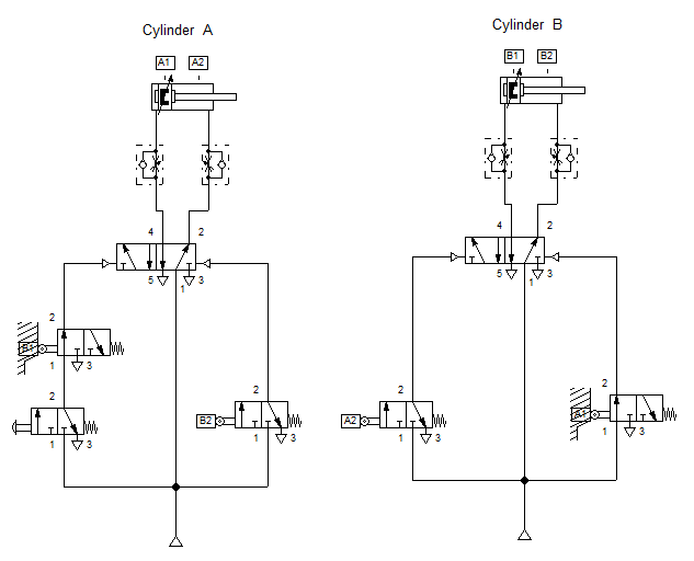
The pneumatic circuit in Figure 1 employs four sensor that acknowledges the action in the cylinders. Each cylinder has a pair of limit switches placed at its full retracted position and extended position. This limit switches serves as the sensing mechanism for each action the cylinder performs. Also, these sensors transmit signal to each 3/2 way directional valve in the circuit to actuate the port at which it is connected. The assignment of each limit switches to the 3/2 way valve are based from statement in the previous section. For example, Cylinder B extends once Cylinder A has fully pushed the box out of the rack. We assigned A2 ( sensor at fully extended cylinder A) so that Cylinder B extends once A2 is hit by the piston head of Cylinder A. A signal is sent to the 3/2 way directional valve to open and actuates Cylinder B. This process follows with the other sensors in the circuit. B2 acknowledges Cylinder 2 is fully extended which causes Cylinder A to retract. A0 and B0 ensures that the initial state is achieved and returns the system to initial state after the push button is pressed.
When the push button is pressed, the air flows to port 14 of the 5/2 way directional valve, pneumatically actuated. This causes a shift between ports 2 and 4. Once port 4 is open, air flows of the 5/2 way DCV through the cylinder and extends it. The one-way flow control valve regulates the flow to the cylinder at 50%. When the piston head of Cylinder A reaches A2, A2 shifts the 3/2 way DCV, which is linking to it, to an open position and allows air to flow across the Cylinder B's 5/2 way DCV. Cylinder B extends as air passes through it. As it reaches its full extension, B2 sends a signal to retract Cylinder A. This can be seen on the simulation in Figure 2. By the way, cylinder B is extend at a regulated speed set by the 50% opening in the one-way flow control valve attached to it.
3. Conclusion
In this text, we discuss how we correctly assigned the sensors of multiple actuators to achieve a correct response. The use of multiple actuators have more practical advantage than its disadvantage. The placement of each sensors in the circuit determines how well the circuit response as to what is defined in the problem or scenario. Overlapping of signal causes the circuit to not run or run incorrectly to what was desired. In the text, we used mechanical sensors via a limit switches but there are more types of sensors that can be employed. Assigning the sensors are quite difficult if mechanism not fully understood. The important thing to remember in sequencing multiple actuators is to correctly define the sequence of operation.
4. References
[1] Pneumatic Basic Level. online access
[2] Pneumatic Advanced Level. online access
(Note: All images and diagram in the text are drawn by the author (@juecoree) except those with separate citation.)
If your are Interested in Pneumatic Basics, you can read the other posting:
1. Pneumatic Basics: Direct Control
2. Pneumatic Basics: Indirect Control
3. Pneumatic Basics: AND and OR Logic
4. Pneumatic Basics: Memory Circuit and Speed Control
5. Pneumatic Basics: Dependent control
Posted with STEMGeeks