1. Introduction
In the previous post, we talked about implementing the AND and OR logic by crating a control circuit for the cutting and tipping device. In this blog, we explore the mechanism of a punching device and discus on how to implement the XOR logic in electro-pneumatic. Also, we elaborate on interlocking and latching in the context of control circuit.
For this blog, we describe the operation of a punching devices as:
A notch is to punched in the workpiece by a pneumatic cylinder. The workpiece is fed from any one of three work stations. The punching operation is to be triggered when 2 sensors emit a signal. The signaling elements a, b and c are installed for sensing. The cylinder returns to its retracted position when the part is pulled out of the device.
The problem asked to create a control circuit that allows a workpiece to be punch by a pneumatic cylinder. The punching mechanism activates once 2 sensor acknowledges the workpiece is in the workstation. If the three sensor is activated at once, the pneumatic cylinder remains retracted. With the condition in mind, we used and XOR logical function to achieve the task of activating the mechanism via 2 sensors. The XOR logic allows activation in the output for the given set of input is not the same. For example an input A = 0 and B = 0 results to a 0 output but A = 1 and B= 0 yield a 1 output.
Furthermore, the XOR function is achieved by interlocking and latching the steps in our control circuit. Interlock mechanism allows one ladder activates while the other is deactivated. On the other hand, latching mechanism sustains the shifting position even the initial actuation was released. In the next section, the circuit and the simulation is discussed.
2. Circuit and Simulation
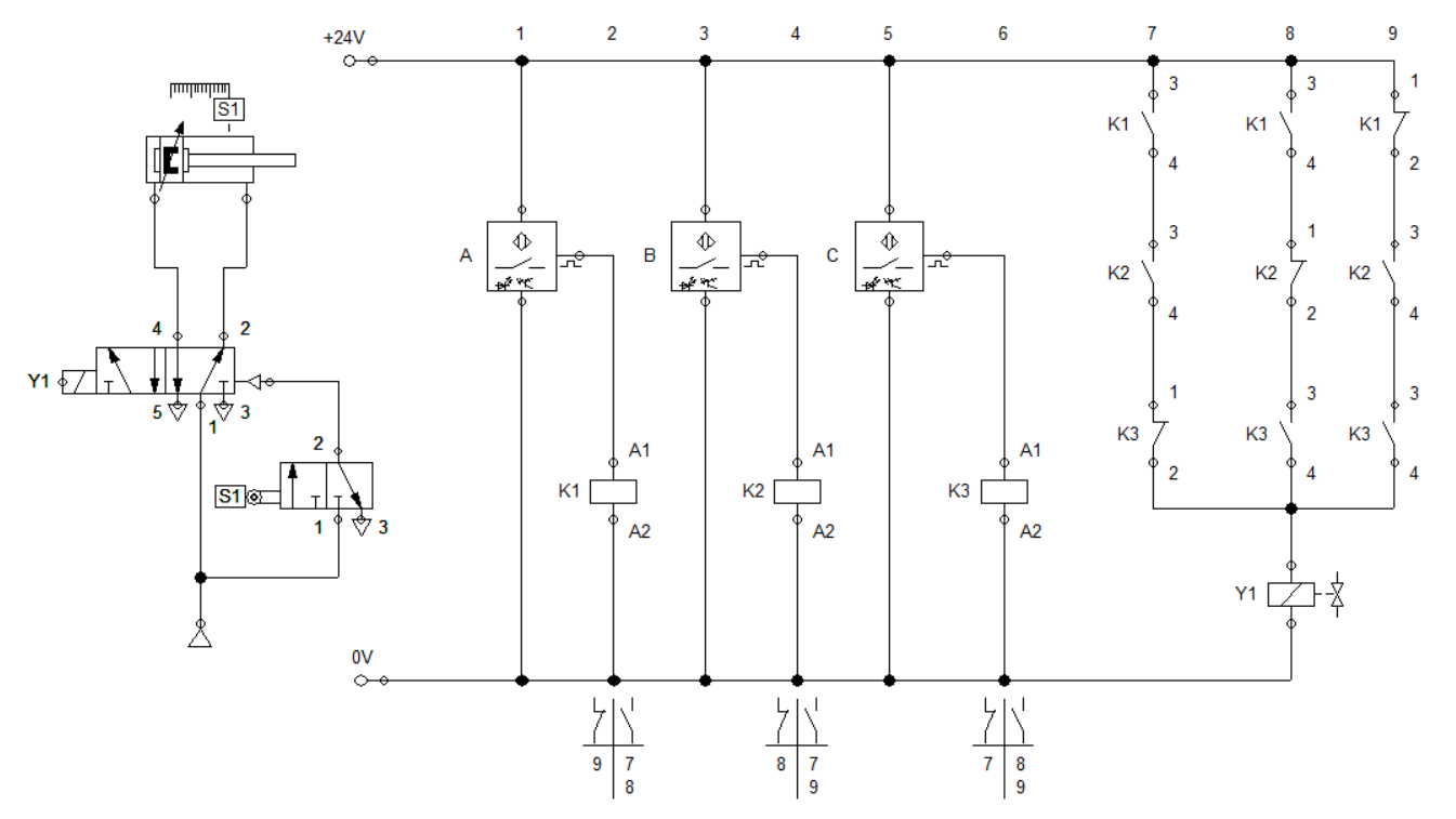
We start by configuring three sensors that causes the cylinder to actuate. There are variety of sensor to be employed but we opt to used optical sensor hence it is more practical for the problem at hand. Each of the sensor is attached to a relay coil that latches to the control mechanism, as shown in Figure 1. The latching cause the contacts for the relay coils in the even with momentary releasing the actuation. Also, the pneumatic actuator circuit is the same with that of the cutting device.
Figure 1: Configuring the sensors
Next, we correctly placed and sequence the latching to the sensor to achieve the desired mechanism. There are three ladders to achieve the XOR logic and perform the required task. Each ladder consist of two normally open contact and a normally closed. The normally closed contact interlocks the circuit so that only two sensor activates the cylinder at any given time. Each ladder or step has different closed contact to ensure that there is no overlapping in the signals. Overlapping the designation of contacts results to non-activation of the solenoid valve Y1.
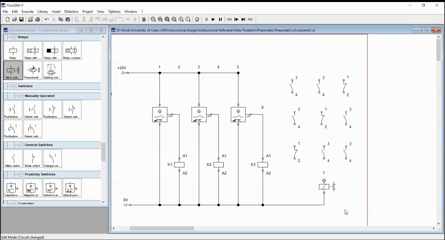
Figure 2: Establishing the XOR logic
Figure 3: Assigning the latching and interlocks.
When the sensor is activates, as shown in Figure 4, The relay coil K1 is energized and the latching contacts K1 at the controller shifted from open to closed or in reverse. This is the same as to the other sensors in the circuit. As you can observed, each ladder or step has a closed contact. For example, for ladder 7, both K1 and K2 are normally open while K3 is normally closed. The closed contact is different in each ladder so that when a pair of contacts is open the solenoid Y1 activates. However, when all contacts are activated the normally closed contact opens to break the flow of current through the solenoid.
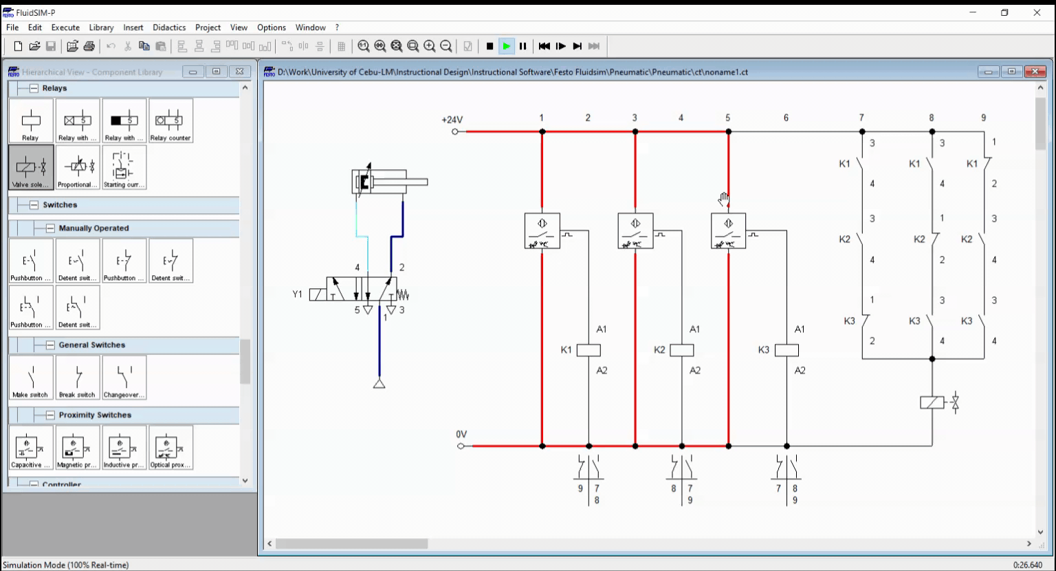
Figure 4. Activating sensors and checking latching mechanism.
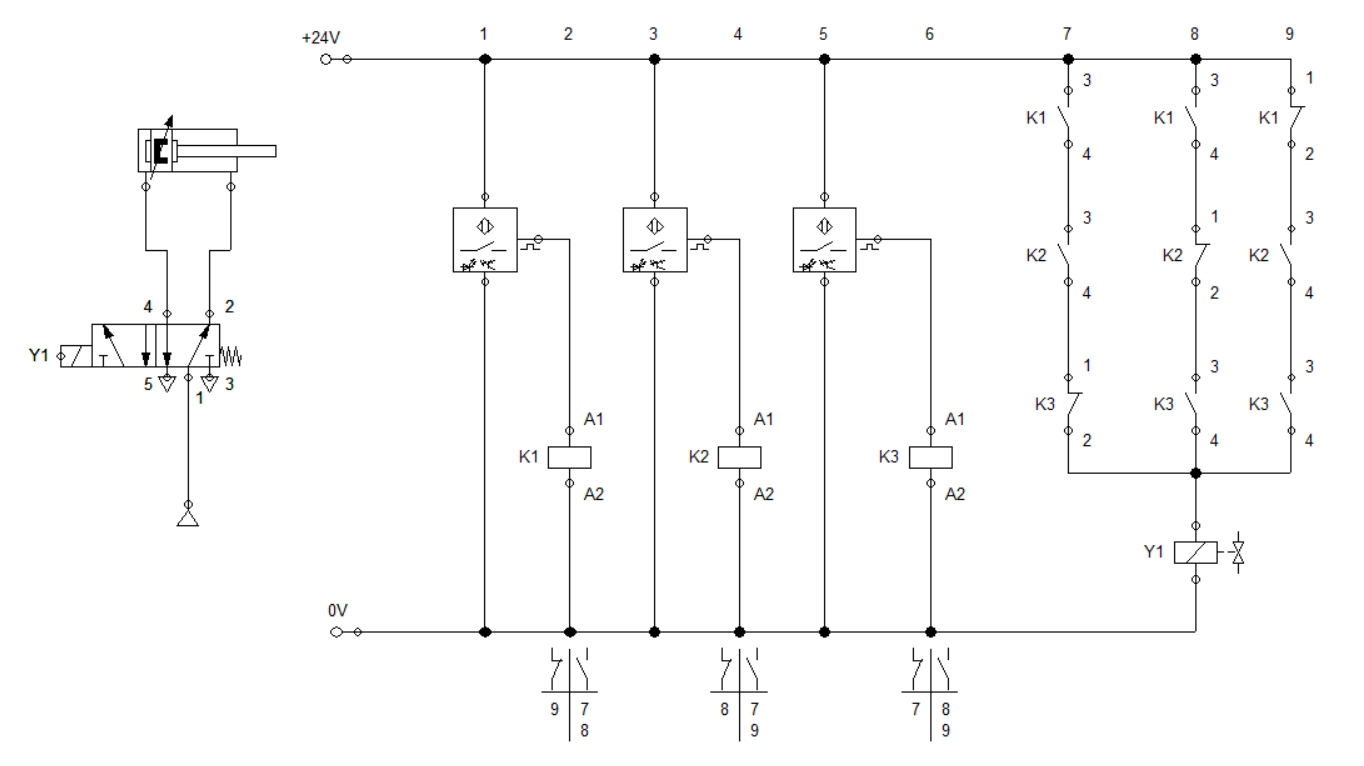 Figure 5: Electro-pneumatic circuit with quick released of cylinder extended position.
When all sensors is activated at the same time, the interlocking mechanism cut the current flow at the solenoid Y1. The circuit does not full extend the cylinder because the sensor latching is deactivated. Once deactivated, the spring return in the 5/2 way DCV shifted the air flow to port 2. To solve this we configure a basic pneumatic memory circuit. In Figure 6, the updated circuit is shown.
Figure 6: Electro-pneumatic circuit for Punching Device
Once the two sensor is activated, the latching mechanism opens the contacts and current flows across solenoid Y1. Hence solenoid Y1 is link to the single solenoid, 5/2 way directional valve, the valve opens port 4 and allows air to extend the cylinder. In Figure 5, the cylinder can not fully extend due to quick released of actuation at the sensor. To solve this problem, we attached a pneumatic memory circuit to achieved the full extension of the double-acting cylinder. The full simulation is shown in Figure 7.
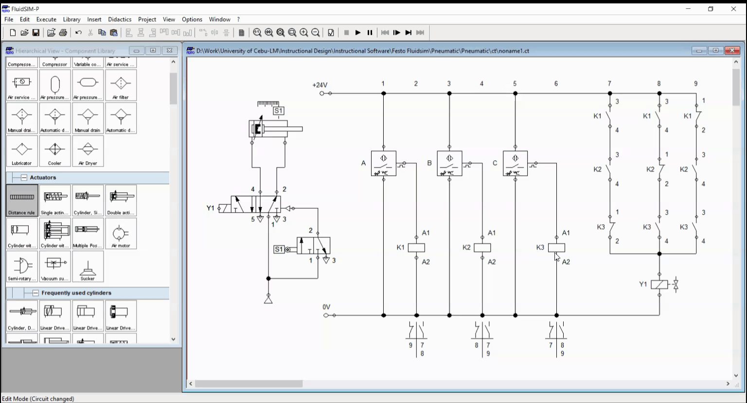
Figure 7: Full Simulation
3. Conclusion
In the punching device, the process needed at two sensors to actuate the double0acting cylinder and if three sensor is simultaneously actuated, the cylinder remain retracted. This is the core condition needed to be interpreted in a electro-pneumatic circuit. The XOR logic was used to achieved the task by using interlocking and latching mechanism, as shown in the figures. The interlocking contacts prevent the cylinder to retract once three sensors are activated. In contrast, latching contacts allows current to flow across the solenoid once the link sensor is activated. Furthermore, the pneumatic circuit was added with a basic pneumatic memory circuit to achieve the full extension.
4. References
[1] Pneumatic Basic Level. online access
[2] Pneumatic Advanced Level. online access
[3] Electro-pneumatic Basic Level. online access
(Note: All images and diagram in the text are drawn by the author (@juecoree) except those with separate citation.)
If your are Interested in pneumatic and electro-pneumatic system, you can read:
1. Pneumatic Basics: Direct Control
2. Pneumatic Basics: Indirect Control
3. Pneumatic Basics: AND and OR Logic
4. Pneumatic Basics: Memory Circuit and Speed Control
5. Pneumatic Basics: Dependent control
6. Pneumatic Basics: Multiple Actuators
7. Electro-pneumatic Basic: AND and OR Logic
Posted with STEMGeeks
Congratulations @juecoree! You have completed the following achievement on the Hive blockchain and have been rewarded with new badge(s) :
You can view your badges on your board and compare yourself to others in the Ranking
If you no longer want to receive notifications, reply to this comment with the word
STOPTo support your work, I also upvoted your post!
Do not miss the last post from @hivebuzz: